F97CMN and G97CMN: Installation, Start-up, Operating and Service and Maintenance Instructions
Manufacturer reserves the right to change, at any time, specifications and designs without notice and without obligations.
33
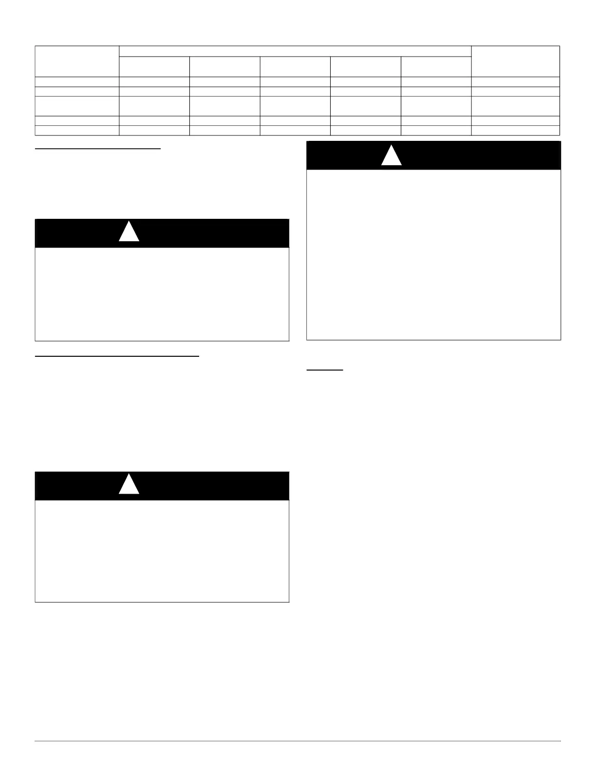
Table 10 – Vent Termination Kit for Direct Vent (2-pipe) Systems
Direct Vent / 2-Pipe System
In a direct-vent (2-pipe) system, all air for combustion is taken directly
from outdoor atmosphere, and all flue products are discharged to outdoor
atmosphere. Combustion-air and vent pipes must terminate together in
the same atmospheric pressure zone, either through the roof (preferred)
or a sidewall. See Fig. 39 for references to clearances required by
National code authorities.
Ventilated Combustion Air Systems
In a ventilated combustion air option, the vent terminates and discharges
the flue products directly to the outdoors similar to a direct vent system.
See Fig. 40 for references to clearances required by National code
authorities.
All air for combustion is piped directly to the furnace from a space that is
well ventilated with outdoor air (such as an attic or crawl space) and the
space is well isolated from the living space or garage. Combustion air
requirements for this option are the same as the requirements for
providing outside air for combustion for a single pipe vent system. Refer
to the “Air For Combustion and Ventilation” Section.
Locating the Vent Termination
General
NOTE: Termination Requirements for the Provinces of Alberta and
Saskatchewan are located at the end of this section.
Combustion-air inlet pipe (direct vent/2-pipe system only) and vent pipe
must terminate outside structure, either through sidewall or roof.
Special termination requirements may be required in other Canadian
provinces. Refer to the authority having jurisdiction for clarification
and/or additional clearance requirements.
For vent termination clearance, references to National codes are shown
in Fig. 39 for Direct Vent/2-Pipe system and Fig. 40 for Ventilated
Combustion Air system. For exterior termination arrangements, refer to
Fig. 38 for Direct Vent/2-Pipe system and Fig. 41 for Ventilated
Combustion Air system. Contact Local code authorities for other
requirements to and/or exemptions from the National codes shown in the
figures.
Roof termination is the recommended termination location. Roof
terminations provide better performance against sustained prevailing
winds. The roof location is preferred since the vent and combustion air
system is less susceptible to damage or contamination. The termination
is usually located away from adjacent structures or other obstacles such
as inside corners, windows, doors or other appliances. It is less prone to
icing conditions, and it often has less visible vent vapors.
Sidewall terminations may require sealing or shielding of building
surfaces with a corrosive resistance material due to the corrosive
properties of combustion products from the vent system, as well as
protection of adjacent structures.
Vent and
Combustion Air Pipe
Diameters
Approved Two-Pipe Termination Fittings
Allowable Concentric
Vent Kit
1 1/2-in.
(38 mm)
2-in.
(51 mm)
2 1/2-in.
(64 mm)
3-in.
(76-mm)
4-in.
(102 mm)
1 1/2-in. (38 mm) No Yes No No No 2-in. (51 mm)
2-in. (51 mm) No Yes No No No 2-in. (51 mm)
2 1/2-in. (64 mm) No No No Yes No
2-in. (51 mm)
3-in. (76 mm)
3-in. (76-mm) No No No Yes No 3-in. (76 mm)
4-in. (102 mm) No No No Yes Yes 3-in. (76 mm)
NOTICE
!
OPTIONAL CONFIGURATION FOR COMBUSTION
AIR INLET PIPE
In applications where there is a risk of excessive moisture entering the
combustion air inlet pipe, a moisture trap may be added to the inlet pipe
to help prevent moisture from entering the furnace from the combustion
air inlet pipe, see Fig. 48.
When sizing venting systems, the equivalent length of the optional inlet
pipe moisture trap must be taken into account.
NOTICE
!
OPTIONAL VENTING BELOW THE FURNACE
The venting system may be positioned below the furnace ONLY IF the
factory accessory External Vent Trap Kit is used. The External Vent
Trap Kit is only approved for PVC/ABS DWV venting systems.
CAREFULLY FOLLOW THE INSTRUCTIONS PROVIDED
WITH THE EXTERNAL VENT TRAP KIT FOR LAYING OUT
THE VENTING SYSTEM AND THE DRAIN SYSTEM. The
instructions included with this furnace DO NOT APPLY to vent
systems that are located below the furnace.
WARNING
!
CARBON MONOXIDE POISONING HAZARD
Failure to follow the instructions outlined below for each appliance
being placed into operation could result in carbon monoxide poisoning
or death.
The instructions included with this furnace DO NOT APPLY to vent
systems that are located below the furnace. CAREFULLY FOLLOW
THE INSTRUCTIONS PROVIDED WITH THE EXTERNAL
VENT TRAP KIT FOR LAYING OUT THE VENTING SYSTEM
AND THE DRAIN SYSTEM when all or part of the venting system is
placed below the furnace.
Proper configuration of the venting and drain system is critical when
placing all or part of the venting system below the level of the furnace.
VENT GASSES COULD BE RELEASED FROM THE
DRAINAGE SYSTEM if the instructions provided with the External
Vent Trap Kit are not followed.
 Loading...


