Communications wiring
Fan Coil CARRIER CORPORATION ©2020
Integration Guide All rights reserved
11
Modbus
To set up the Fan Coil for Modbus RTU
1 Turn off the power for the Fan Coil by disconnecting power terminals.
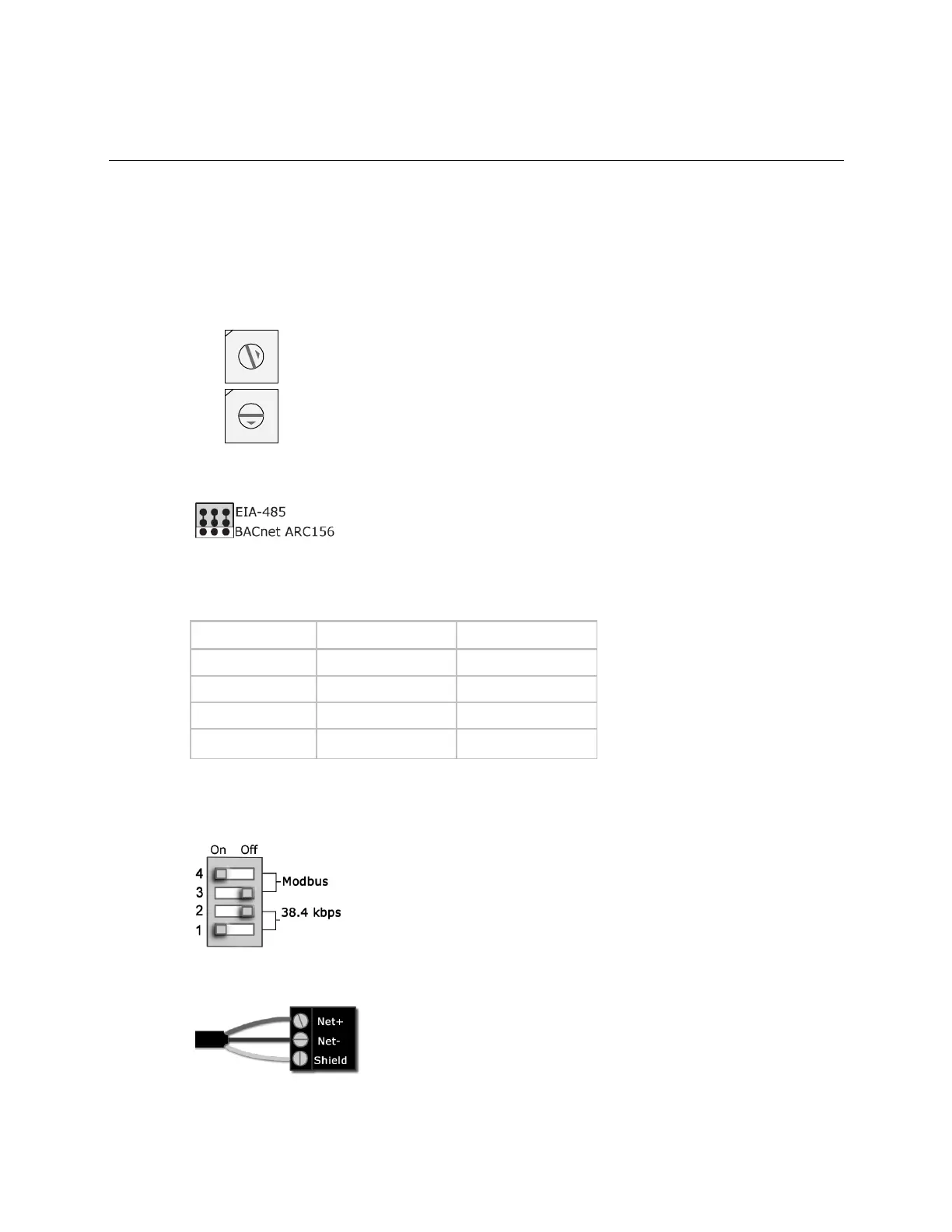
2 Using the rotary switches, set a unique address. Set the Tens (10's) switch to the tens digit of the address,
and set the Ones (1's) switch to the ones digit.
EXAMPLE If the controller’s address is 25, point the arrow on the Tens (10's) switch to 2 and the arrow on
the Ones (1's) switch to 5.
NOTE The Fan Coil recognizes its address only after power has been cycled.
3 Set communications selector for EIA-485.
4 Set DIP switches 1 and 2 for the appropriate communications speed. See table below.
NOTE Use the same baud rate for all devices on the network segment.
5 Set DIP switch 3 OFF and 4 ON for Modbus.
The following example is set for 38.4 kbps and Modbus.
6 Connect the communications wiring to the Comm port in the screw terminals labeled Net +, Net -, and Shield.

 Loading...