33
PRE-START-UP
Do not attempt to start the air-conditioning system until the
following checks have been completed.
System Check
1. Check all system components, including the air-handling
equipment. Consult manufacturer's instructions. If the
unit has field-installed accessories, be sure all are proper-
ly installed and wired correctly. Refer to unit wiring
diagrams.
2. Open liquid line and suction line service valves.
3. Check tightness of all electrical connections.
4. Oil should be visible in the compressor sight glasses. An
acceptable oil level in the compressor is from
1
/
8
to
3
/
8
of
sight glass. Adjust the oil level as required. No oil should
be removed unless the crankcase heater has been ener-
gized for at least 24 hours. See Add Oil section on
page 47, for Carrier-approved oils.
5. Electrical power source must agree with unit nameplate.
6. Crankcase heaters must be firmly attached to compres-
sors, and must be on for 24 hours prior to start-up.
7. Fan motors are 3-phase. Check rotation of fans during
first start-up check.
EVACUATION AND DEHYDRATION — Because the
38AP systems use polyolester (POE) oil, which can absorb
moisture, it is important to minimize the amount of time that
the system interior is left exposed to the atmosphere. Minimiz-
ing the exposure time of the oil to the atmosphere will mini-
mize the amount of moisture that needs to be removed during
evacuation.
Once all of the piping connections are complete, leak test
the unit and then pull a deep dehydration vacuum. Connect the
vacuum pump to the charging valve in the suction line and to
the liquid line service valve. For best results, it is recommended
that a vacuum of at least 500 microns (0.5 mm Hg) be ob-
tained. Afterwards, to ensure that no moisture is present in the
system, perform a standing vacuum-rise test.
With the unit in deep vacuum (500 microns or less), isolate
the vacuum pump from the system. Observe the rate-of-rise of
the vacuum in the system. If the vacuum rises by more than
50 microns in a 30-minute time period, then continue the dehy-
dration process. Maintain a vacuum on the system until the
standing vacuum requirement is met. This will ensure a dry
system.
By following these evacuation and dehydration procedures,
the amount of moisture present in the system will be mini-
mized. It is required that liquid line filter driers be installed
between the condenser(s) and the expansion devices to capture
any foreign debris and provide additional moisture removal
capacity.
START-UP
Compressor crankcase heaters must be on for 24 hours be-
fore start-up. To energize the crankcase heaters, close the field
disconnect and turn on the fan circuit breakers. Leave the com-
pressor circuit breakers off/open. The crankcase heaters are
now energized.
Preliminary Charge — Refer to GTAC II (General
Training Air Conditioning), Module 5, Charging, Recovery,
Recycling, and Reclamation for charging procedures. Using
the liquid charging method and charging by weight procedure,
charge each circuit with the amount of Puron
®
refrigerant
(R-410A) listed in Table 15.
IMPORTANT: Before beginning Pre-Start-Up or Start-Up,
review Start-Up Checklist at the back of this publication.
The checklist assures proper start-up of a unit and provides
a record of unit condition, application requirements, system
information, and operation at initial start-up.
IMPORTANT: Before beginning Pre-Start-Up or Start-Up,
review Start-Up Checklist at the back of this publication.
The checklist assures proper start-up of a unit and provides
a record of unit condition, application requirements, system
information, and operation at initial start-up.
CAUTION
Crankcase heaters on all units are wired into the control cir-
cuit, so they are always operable as long as the main power
supply disconnect is on (closed), even if any safety device
is open. Compressor heaters must be on for 24 hours prior
to the start-up of any compressor. Equipment damage
could result if heaters are not energized for at least 24 hours
prior to compressor start-up.
(F)
90
80
70
60
50
40
30
20
10
0
(C)
32.2
26.7
21.1
15.6
10.0
4.4
-1.1
-6.7
-12.2
-17.8
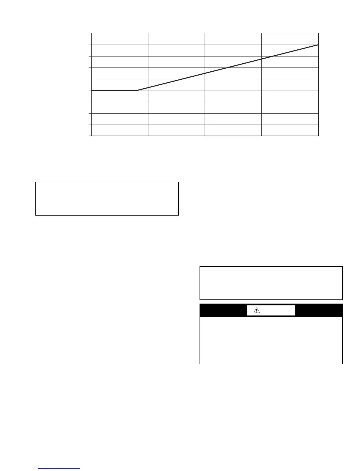
SUPPLY SETPOINT
0 5 10 15 20
SETPOINT SIGNAL – 4-20 mA INPUT
Fig. 34 — 4 to 20 mA Supply Set Point