— 8 —
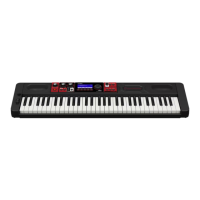
■ To remove the main PCB (M706-MD1).
6. Remove three screws on the PCB (M706-MD1).
7. Remove four connectors by soldering.
8. Remove the PCB (M706-MD1).
■ Precaution while assembling the main PCB (M706-MD1).
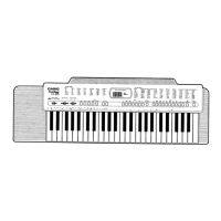
Number of pins on the PCB and pins on the cable are different.
Start connecting from the NO.1 pin whose color is orange.
11 pin cable
CN2 Connector (13pin)
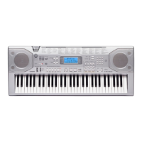
■ To remove the sub PCB (M706-PSA1).
9. Remove five screws on the PCB (M706-PSA1).
10. Remove two connectors by soldering.
11. Remove five lead wires by soldering.
12. Remove the PCB (M706-PSA1).
Connector (CN7)
Connector (CN8)
Connector (CN2)
Connector (CN1)
Connector (CN9)
Connector (CN3)
Lead wire (orange)
Speaker cord (blue)
Speaker cord (brown)
Speaker cord (green)
Speaker cord (white)
 Loading...