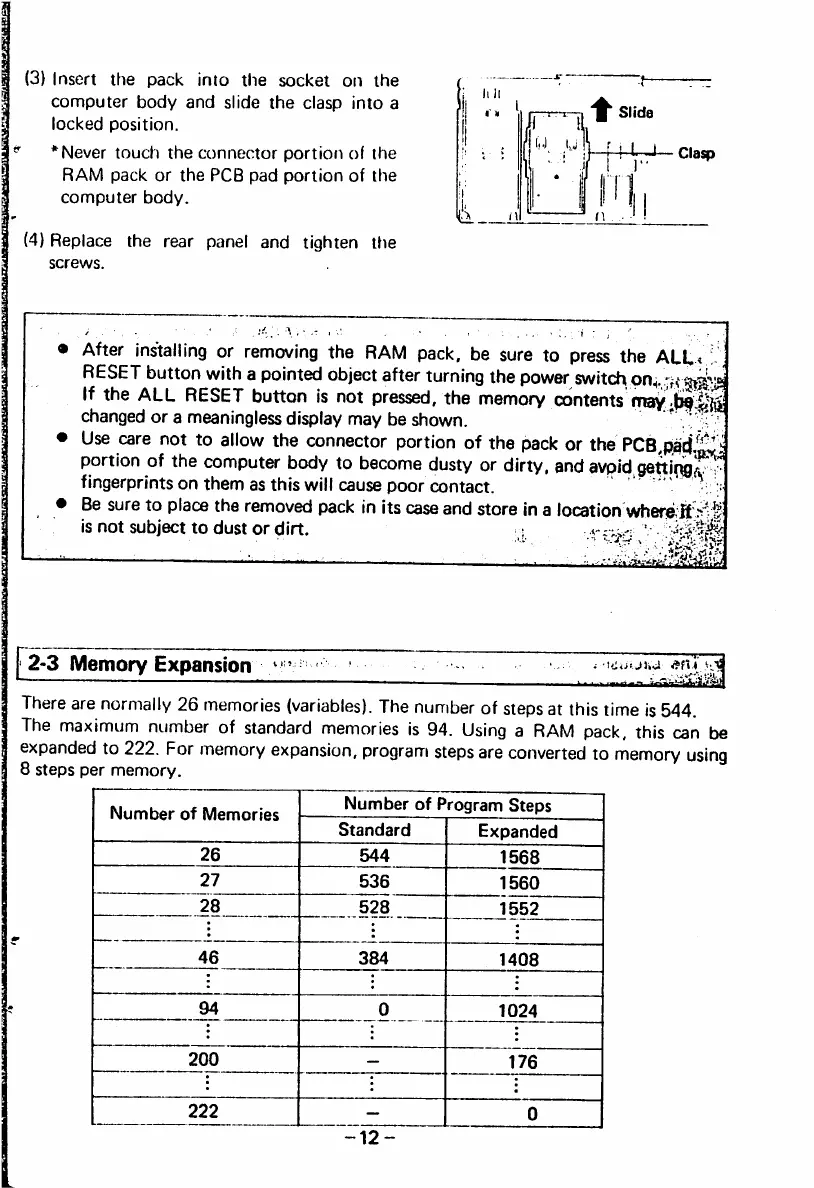
(3) Insert the pack into the socket on the
computer body and slide the clasp into a
locked position.
* Never touch the connector portion of the
RAM pack or the PCB pad portion of the
computer body.
(4) Replace the rear panel and tighten tfie
screws.
ill Hi
■f— Clasp
After installing or removing the RAM pack, be sure to press the ALL.
RESET button with a pointed object after turning the power switc^t on.;, ^
If the ALL RESET button is not pressed, the memory contents may
c h a n g e d o r a m e a n i n g l e s s d i s p l a y m a y b e s h o w n . . ' ;
Use care not to allow the connector portion of the pack or the PCB,R3ci,^'^
portion of the computer body to become dusty or dirty, and avpid
fingerprints on them as this will cause poor contact. ' > <«• n
Be sure to place the removed pack in its case and store In a location where ft
i s n o t s u b j e c t t o d u s t o r d i r t . : % 4 v
2-3 Memory Expansion
There are normally 26 memories (variables). The number of steps at this time is 544.
The maximum number of standard memories is 94. Using a RAM pack, this can be
expanded to 222. For memory expansion, program steps are converted to memory using
8 steps per memory.
Nu m be r o f M e mo r ie s
Number of Program Steps
Standard Expanded
544 1568
536 1560
528 ' 1552
 Loading...