- 4 -
6. CIRCUIT EXPLANATION
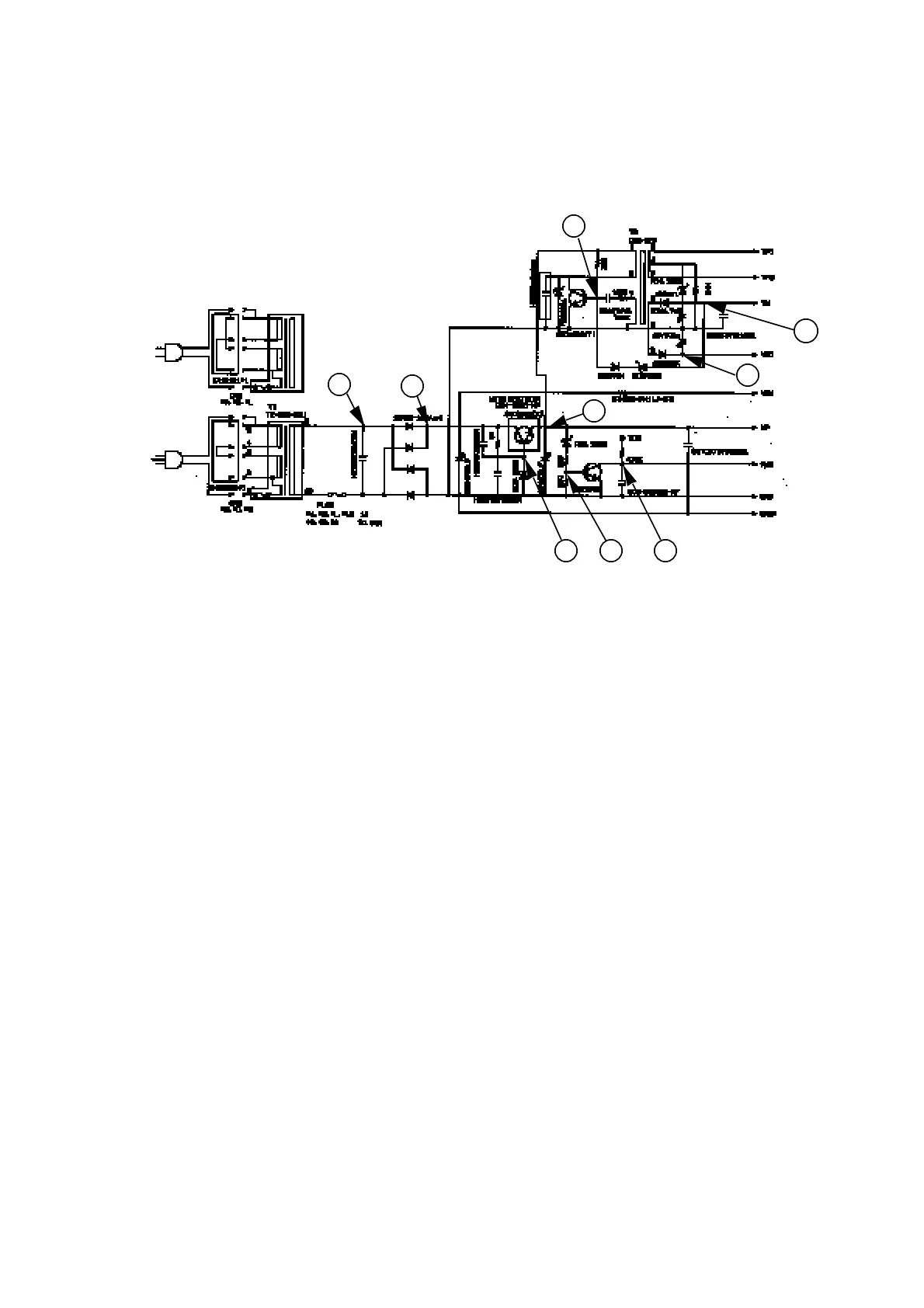
6-1. Power supply circuit
1. Plug the power cord into AC outlet, secondary voltage (9.65VAC) of the power transformer T1
will be appears at "A" point.
2. Then, its AC voltage is rectified by the diode bridge and change it to DC voltage.("B" point)
3. DC voltage appears more than 7V at the corrector of power transistor 2SD2396, and then
the power transistor is turned on.
Then VP is supplied. ("C" point)
4. When the VP voltage becomes more than 3.3V, the transistor 2SD945 is turned on and then
PWD signal becomes GND level. ("F" point)
When the PWD signal becomes GND level, CPU knows no power failure.
5. VP is supplied at the DC DC converter trans T2, the DC DC converter makes display and logic
circuit voltage.
VN ,VF1,VF2 : Display voltage ("I", "J" point )
VDD : Logic circuit voltage ("H" point)
Transistor 2SD1803 is used for oscillating the primary voltage of DC DC converter trans.
A
B
C
D E
F
H
G
I
 Loading...