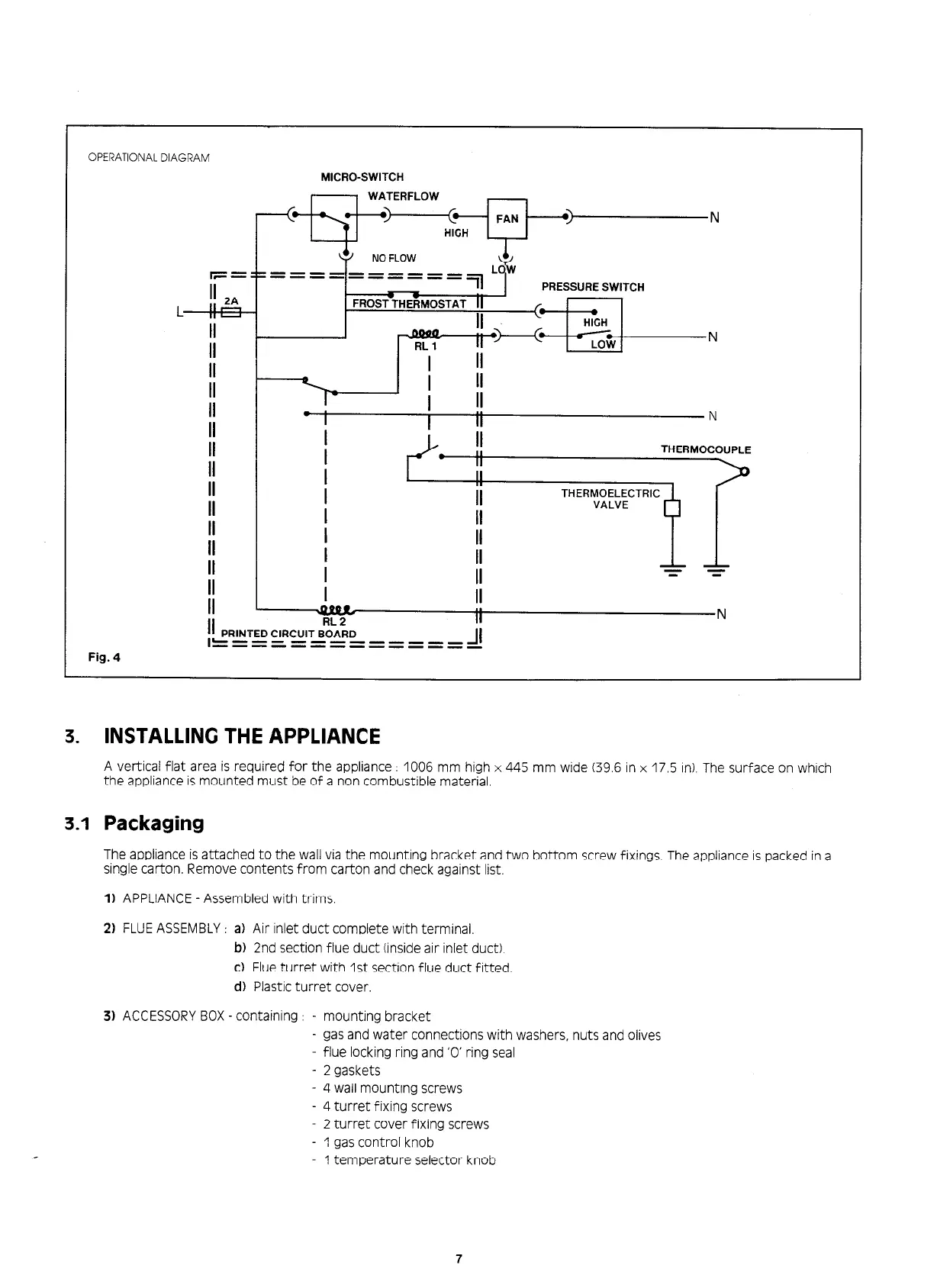
OPERATIONAL DIAGRAM
MICRO-SWITCH
;I 2A
L ,,:
II
II
II
II
II
II
PRESSURE SWITCH
I
II
I
II
I
II
N
ii
II
II
II
II
II
I
.
I
II
I
I
I
I
I
II
T
I
II
Fig. 4
3.
INSTALLING THE APPLIANCE
A vertical flat area is required for the appliance : 1006 mm high x 445 mm wide (39.6 in x 17.5 In). The surface on which
the appliance is mounted must be of a non combustible material.
3.1
Packaging
The appliance is attached to the wall via the mounting bracket and two bottom screw fixings. The appliance is packed in a
single carton. Remove contents from carton and check against list.
1) APPLIANCE - Assembled with trims.
2) FLUE ASSEMBLY : a) Air inlet duct complete with terminal.
b) 2nd section flue duct (inside air inlet duct).
c) Flue turret with 1st section flue duct fitted
d)
Plastic turret cover.
3) ACCESSORY BOX - containing : - mounting bracket
- gas and water connections with washers, nuts and olives
- flue locking ring and ‘0’ ring seal
- 2 gaskets
- 4 wall mounting screws
- 4 turret fixing screws
2 turret cover fixing screws
- 1 gas control knob
1 temperature selector knob
7
 Loading...