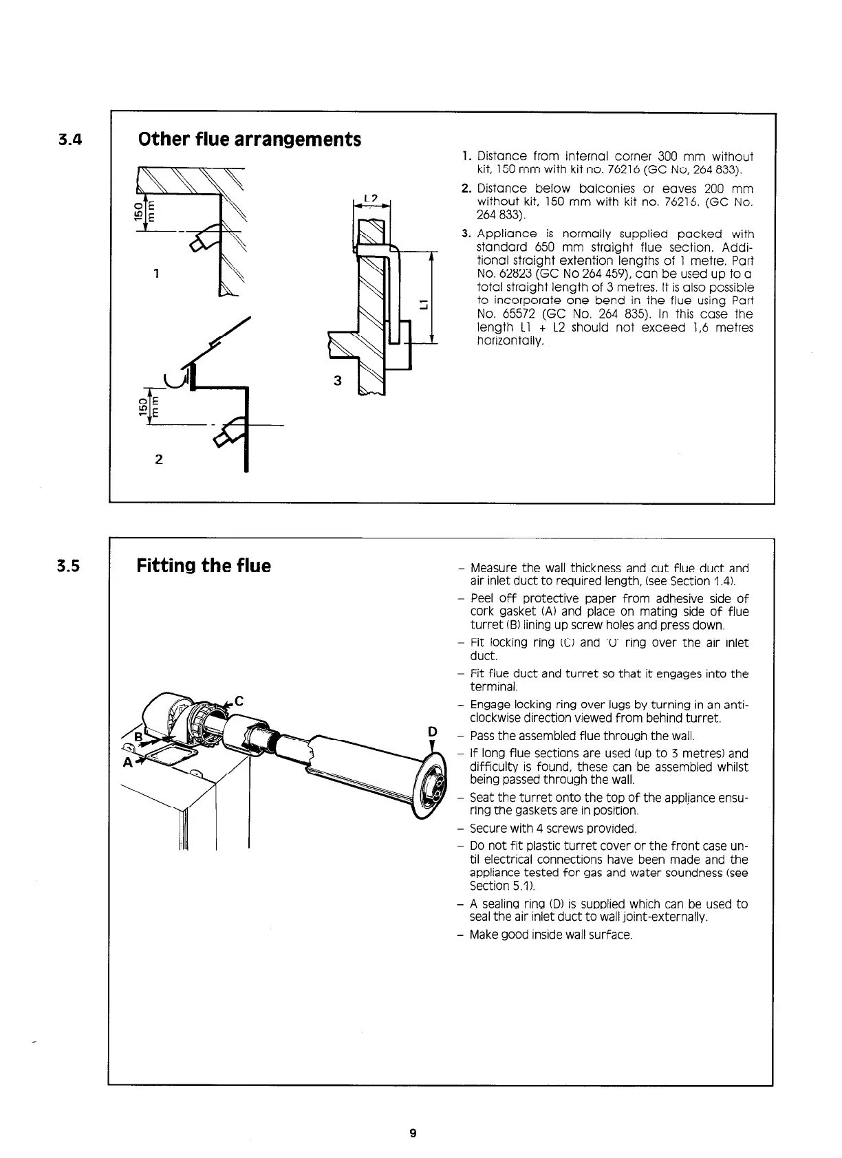
3.4
Other flue arrangements
d
OE
CE
II---
3.5
Fitting the flue
1. Distance from internal corner 300 mm without
kit, 150 mm with kit no. 76216 (GC No, 264 833).
2. Distance below balconies or eaves 200 mm
without kit, 150 mm with kit no. 76216. (GC No.
264 833).
3. Appliance is normally supplied packed with
standard 650 mm straight flue section. Addi-
tional straight extention lengths of 1 metre. Part
No. 62823 (GC No 264 459). can be used up to a
total straight length of 3 metres. It is also possible
to incorporate one bend in the flue using Part
No. 65572 (GC No. 264 835). In this case the
length Ll + L2 should not exceed 1,6 metres
horizonially.
- Measure the wall thickness and cut flue duct and
air inlet duct to required length, (see Section 1.4).
- Peel off protective paper from adhesive side of
cork gasket (A) and place on mating side of flue
turret(B) lining up screw holes and press down.
- Wcpcking ring 0 and ‘0’ ring over the air inlet
- Fit flue duct and turret so that it engages into the
terminal.
- Engage locking ring over lugs by turning in an anti-
clockwise direction viewed from behind turret.
D - Pass the assembled flue through the wall.
- If long flue sections are used (up to 3 metres) and
difficulty is found, these can be assembled whilst
being passed through the wall.
- Seat the turret onto the top of the appljance ensu-
ring the gaskets are in position.
- Secure with 4 screws provided.
- Do not fit plastic turret cover or the front case un-
til electrical connections have been made and the
appliance tested for gas and water soundness (see
Section 5.1).
- A sealing ring (D) is supplied which can be used to
seal the air inlet duct to wall joint-externally.
- Make good inside wall surface.
9
 Loading...