Installing and Upgrading Internal Modules and FRUs in Cisco 1900 Series ISRs
Modules Internal to the Cisco 1941 Router
13
Installing and Upgrading Internal Modules and FRUs in Cisco 1900 Series ISRs
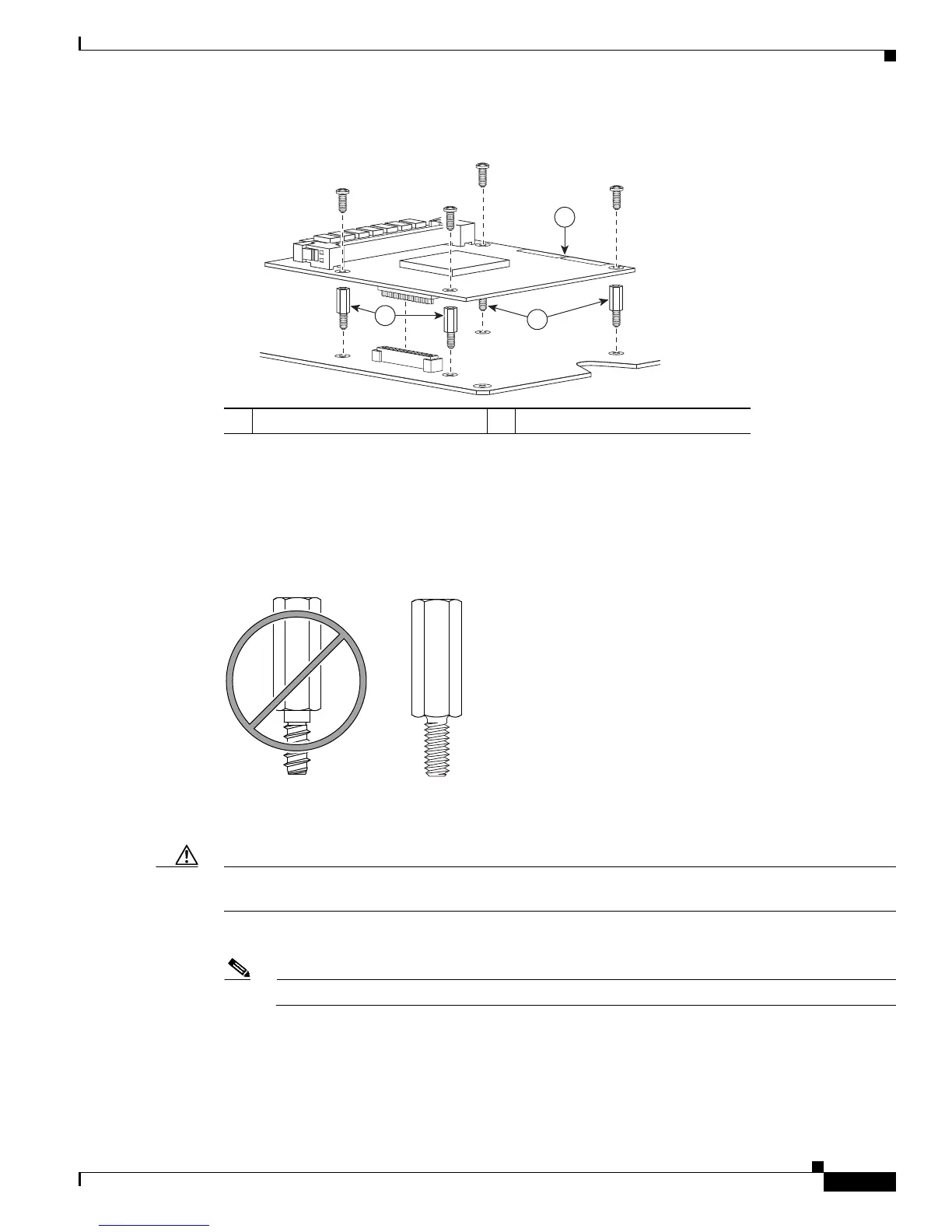
Figure 9 Connecting the ISM to the Cisco 1900 Series System Board
Step 2 Remove the four screws from the system board and keep them. The screws will be used to install the ISM
on the standoffs in Step 3.
Step 3 Locate the four machine-thread standoffs from the accessory kit. (See Figure 10.)
Figure 10 Metal Standoffs
Step 4
Install the four machine-thread metal standoffs into the system board in place of the four screws removed
in Step 2, as shown in Figure 9. Use a 1/4-inch nut driver to tighten the standoffs. Torque the standoffs
to 6 to 8 in-lb (0.68 to 0.90 N-m).
Caution Make sure that the standoffs are straight when installed. Tighten them gently but firmly. Torque them to
6 to 8 in-lb (0.68 to 0.90 N-m). The shoulder must be seated tightly against the system board.
Step 5 Insert the connector on the ISM into the ISM connector on the system board. (See Figure 9.)
Note Be sure to press firmly on the ISM until the board seats onto the connector. (See Figure 9.)
Step 6 Insert the screws through the ISM into the metal standoffs. (See Figure 9.) Carefully tighten the screws
with a Phillips screwdriver. Torque the screws to 6 to 8 in-lb (0.68 to 0.90 N-m).
1 ISM 2 Standoffs (4)
250948
1
2
2
 Loading...