18
Cisco 2500 Series Wireless Controller Getting Started Guide
Installing the Controller
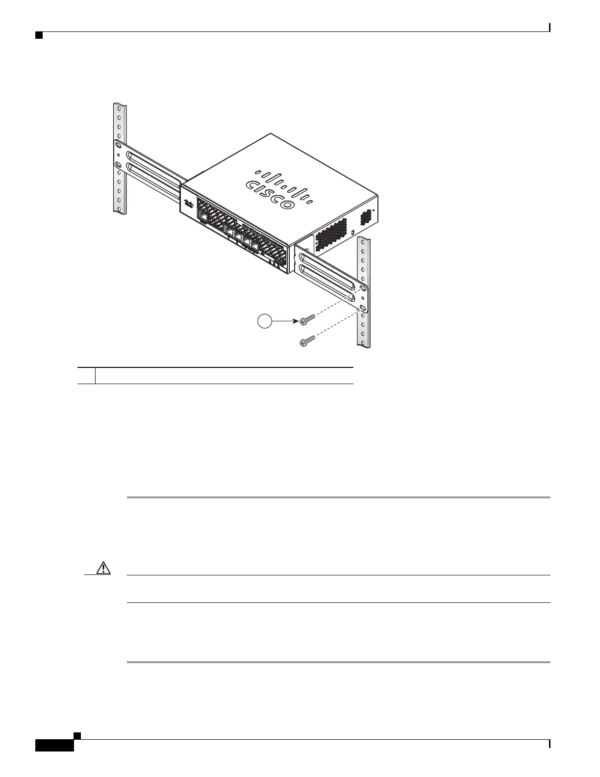
Figure 10 Mounting the Controller in a 19-Inch Rack
Step 3 After the controller is mounted in the rack, perform the following tasks to complete the installation:
• Connecting the Controller Console Port
• Securing the Power Adapter Cable
• Connecting to the Network
Step 4 For configuration instructions about using the CLI setup program, see the “Running the Bootup Script
and Power-On Self Test” section on page 20.
Connecting the Controller Console Port
Caution Do not connect a Power over Ethernet (PoE) cable to the console port. Doing so will damage the
controller.
Before you can configure the 2504 controller for basic operations, you need to connect it to a PC that
uses a VT-100 terminal emulator (such as HyperTerminal, ProComm, Minicom, or Tip). To connect the
PC to the controller console port, follow these steps:
Step 1 Plug the RJ-45 connector on a null-modem serial cable into the controller console port and the other end
of the cable into the serial port of the PC.
1 #10-32 pan-head screws or #12-24 slotted head screws
1
282086
 Loading...