6-47
Hardware Installation Guide for Cisco 4000 Series Integrated Services Routers
OL-32185-02
Chapter 6 Install and Upgrade Internal Modules and FRUs
Remove and Replace Cisco 4000 Series ISRs Power Supplies
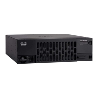
Figure 6-33 Stripped DC Input Power Source Wire
Warning
An exposed wire lead from a DC input power source can conduct harmful levels of electricity. Be
sure that no exposed portion of the DC input power source wire extends from the terminal block.
Statement 122
Step 4 Identify the positive and negative feed positions for the terminal block connection. The wiring sequence
is:
1. Positive (+) lead wire (right)
2. Negative (–) lead wire (left)
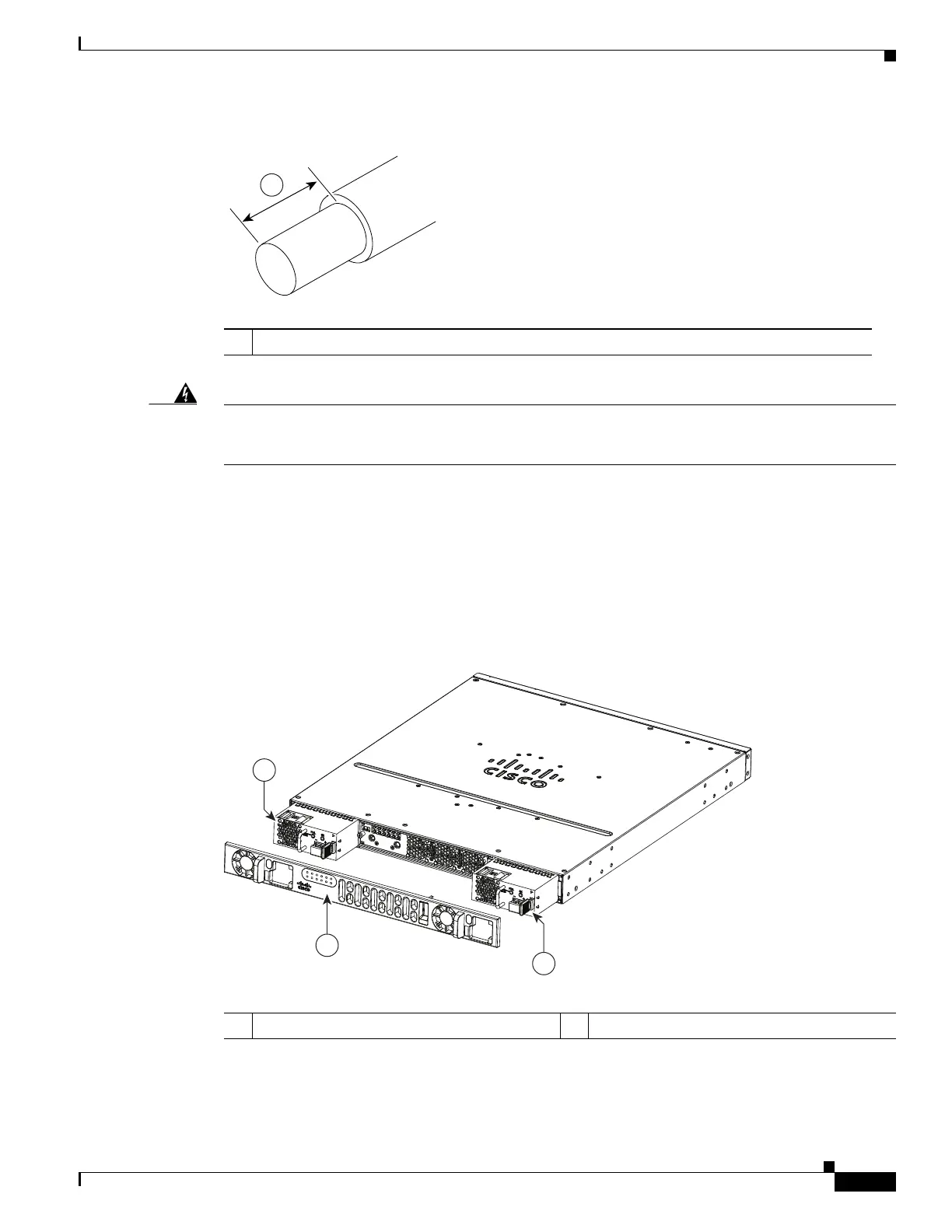
Step 5 Remove the router bezel. See Figure 6-34. The bezel is secured with snap latches. To remove the bezel,
hold the top and bottom and pull the bezel.
Figure 6-34 Remove the Bezel
Step 6 Insert the wires through the holes in the bezel. Replace the bezel.
1 0.39 inch (10 mm) is the recommended wire-strip length for the terminal block.
1 Bezel 2 DC power supplies
 Loading...