1-8
Cisco ASR 920 Series Aggregation Services Router Hardware Installation Guide
OL-32751-01
Chapter 1 Cisco ASR 920 Series Aggregation Services Router Overview
Cisco ASR 920 Router Features
Note This is a debug-only port. it is recommended that this port be used by field service engineers only.
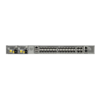
Power Supply and Fans
The Cisco ASR 920 routers support either AC or DC power supplies in a 1+1 redundant configuration.
Note The power supply units are built-in and are not modular.
Note This product requires surge protection as part of the building installation. To comply with the Telcordia
GR-1089 NEBS standard for electromagnetic compatibility and safety, an external surge protective
device (SPD) is required at the AC power service equipment.
Note For DC systems, if a surge of more than 500 V is expected, add an appropriate external surge protective
device.
The Cisco ASR 920 routers have fixed fans are part of the system. The system is designed to operate at
its maximum operating temperature of 70º C and at 65º C in case of failure of a single fan, for a maximum
of four hours. The fan is not removable and in case of a failure, the system must be replaced.
Caution In case of power supply or fan failure, it is highly recommended to let a Cisco technician replace the
router.
LED Indicators
This section describes the different types of LEDs and their behavior.
PWR and STAT LEDs
The PWR and STAT LEDs are available on the front panel. These LEDs provide power on the board
(PWR) and overall router health (STAT) status. During power up state, these LEDs provide booting
status and report errors.
Table 1-2 Power Supply Specification
Specification AC DC
Voltage 100 V – 240 V 24 V – 60 V
Current 2A through a standard C16 type
receptacle
6A through a three-position terminal block
Input Power 115 W
(ASR-920-12CZ-A/ASR-920-4SZ-A)
105 W
(ASR-920-12CZ-D/ASR-920-4SZ-D)

 Loading...