Insecure mounting might damage the ATA or cause injury. Cisco is not responsible for damages incurred
byinsecure wall-mounting.
Note
Procedure
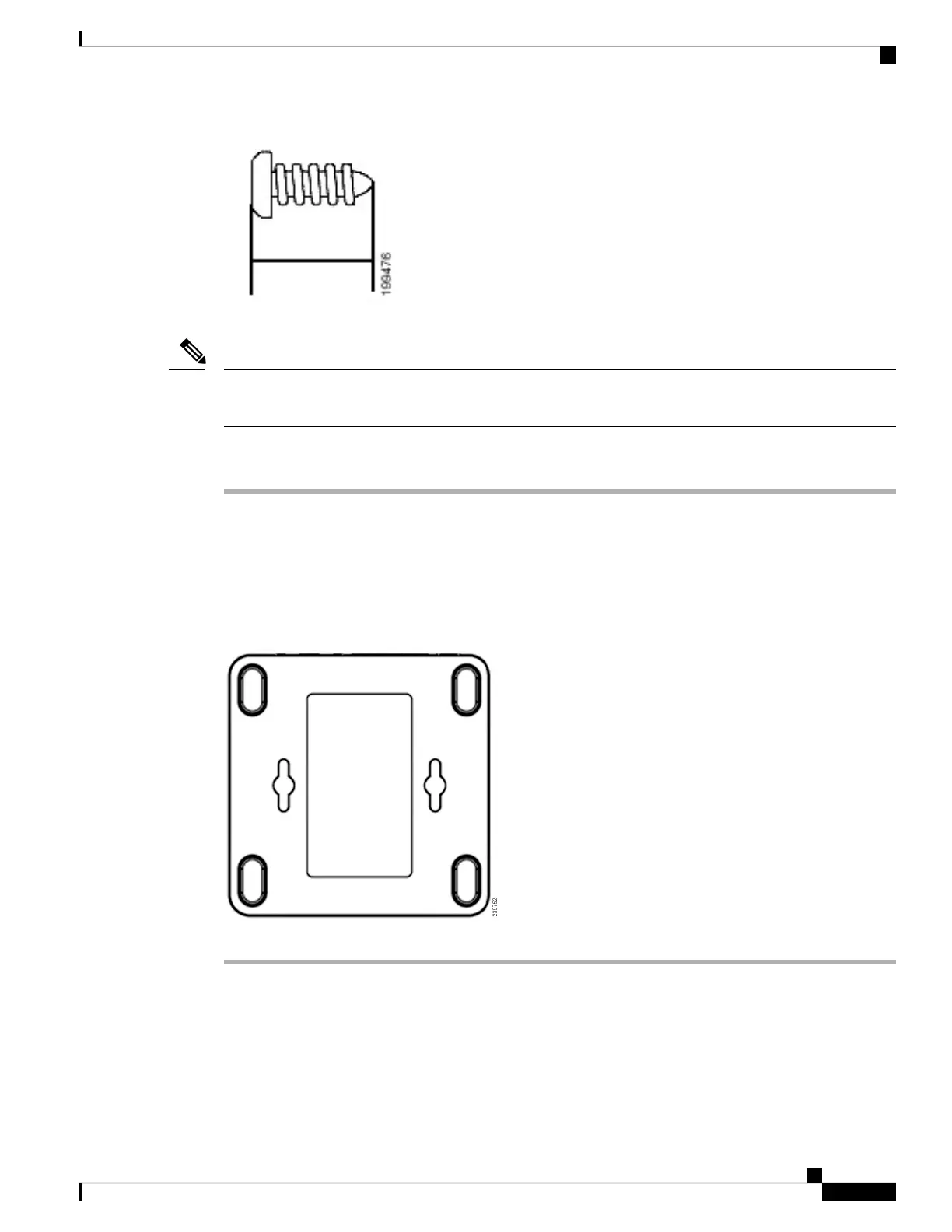
Step 1 Determine where you want to mount the unit. Verify that the surface is smooth, flat and dry.
Step 2 Drill two pilot holes into the surface 58 mm apart (about 2.28 in.).
Step 3 Insert a screw into each hole, leaving a gap of 5 mm (0.1968 in.) between the underside of each screw head
and the surface of the wall.
Step 4 Place the unit wall-mount slots over the screws and slide the unit down until the screws fit snugly into the
wall-mount slots.
Supported ATA Call Features
Depending on your system configuration, your ATA supports some or all the following call features:
Get Started with Your New ATA
7
Get Started with Your New ATA
Supported ATA Call Features
 Loading...