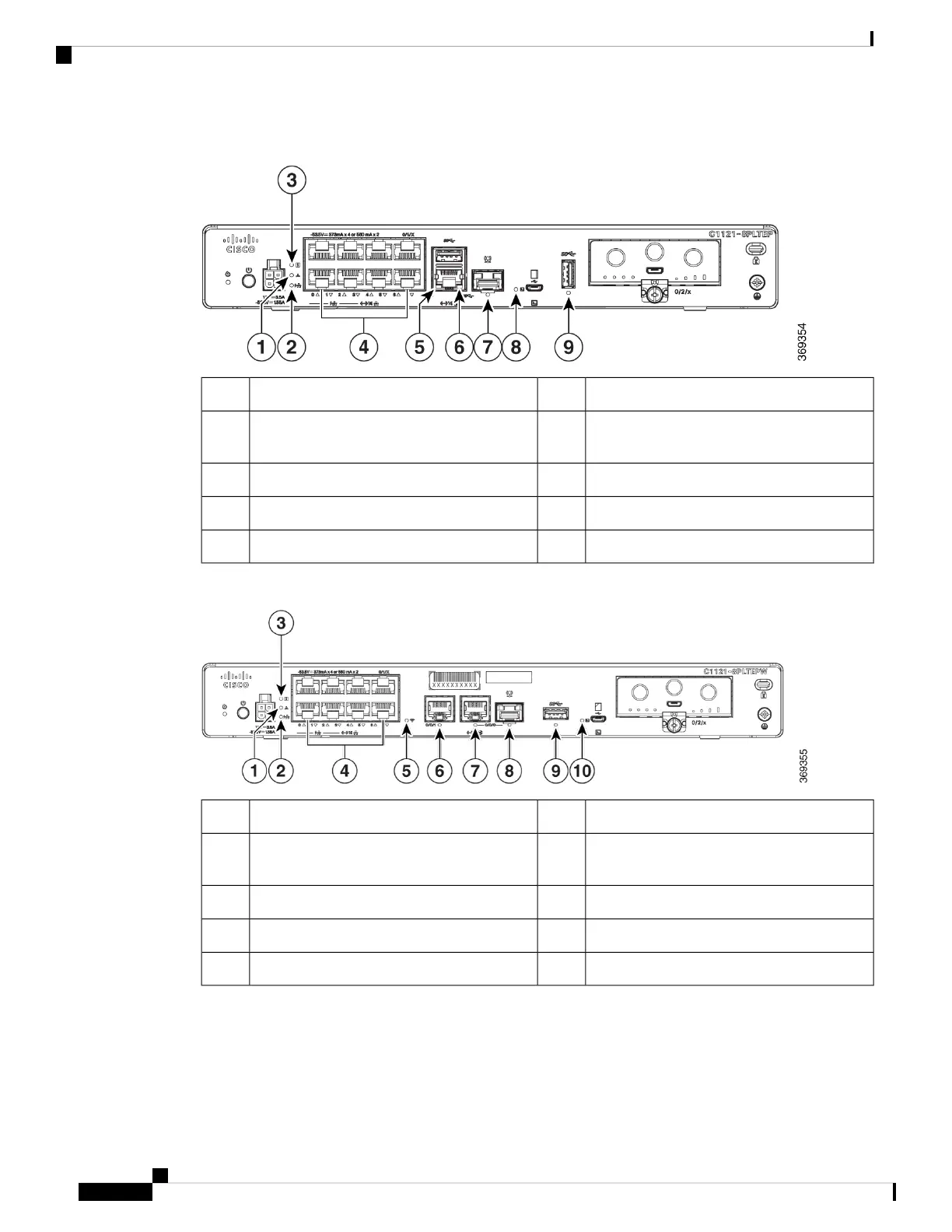
Figure 26: Cisco 11x1(X)-8P/ C11x1(X)-8PLTEP LED Indicators
PoE LED2VPN1
Ethernet Switch Ports 0-7 (0,2,4,6 at the top
and 1,3,5,7 at the bottom)
4Status3
GE 0/0/1 LED6GE 0/0/0 RJ45 LED5
Micro USB Console LED8GE 0/0/0 RJ45 LED7
USB LED9
Figure 27: Cisco 11x1(X)-8PLTEPWx LED Indicators
PoE LED2VPN1
Ethernet Switch Ports 0-7 (0,2,4,6 at the top
and 1,3,5,7 at the bottom)
4Status3
GE 0/0/0 RJ45 LED6Wi-Fi5
GE 0/0/0 SFP LED8GE 0/0/1 LED7
Micro USB Console LED10USB LED9
Hardware Installation Guide for the Cisco 1000 Series Integrated Services Router
14
Overview of Cisco 1000 Series Integrated Services Routers
LED Indicators
 Loading...