2-37
Cisco Integrated Services Router Hardware Installation Guide
Chapter 2 Installing the Router
Installing the Cisco 810 ISR
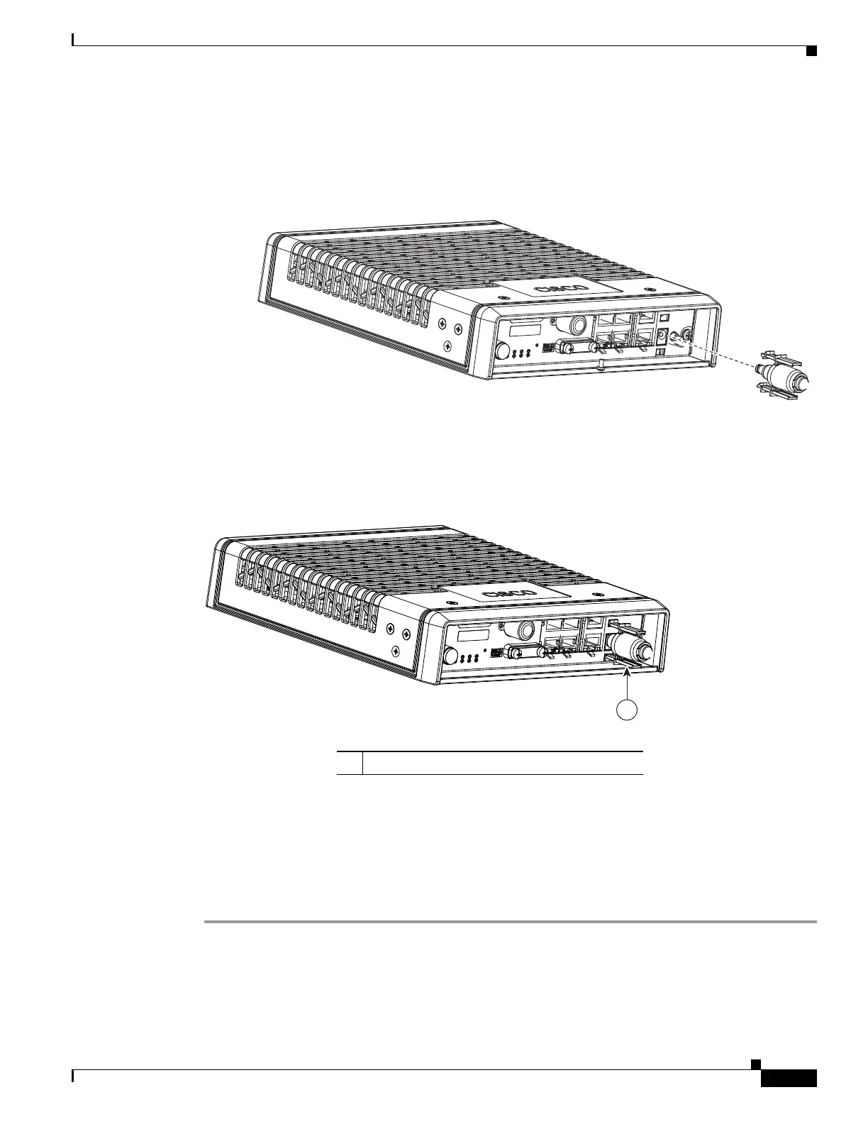
Step 3 Install the power cord with power cord lock and the pre-installed o-ring to mate with the power jack on
the router while making sure that the two arms of the power cord lock slide into the corresponding slots
on the router and are fully seated with both arms locking into the slots as shown in Figure 2-36.
Figure 2-36 Installing Power Cord Lock onto the Router
Step 4 To remove the power cord lock, use your thumb and index fingers to squeeze ends of tabs while pulling
away from the router. (See Figure 2-37.)
Figure 2-37 End of Tabs
Installing the Power Switch Lock
The Cisco 819 ISRs have a power switch lock as an accessory. The power switch lock prevents
unauthorized access to a tampered proof router (for example, router in a bus). For the complete list of
Cisco 819 ISRs that support power switch lock, see Table 1-7.
This section describes how to install the power switch lock.
Step 1 Install the power switch lock by following the parts listed in Figure 2-38.
All these parts are in the accessory kit in their own bag. The ring terminal does not have to be installed.
Figure 2-39 shows the power switch lock installed.
285517
285518
1
1 End of tabs
 Loading...