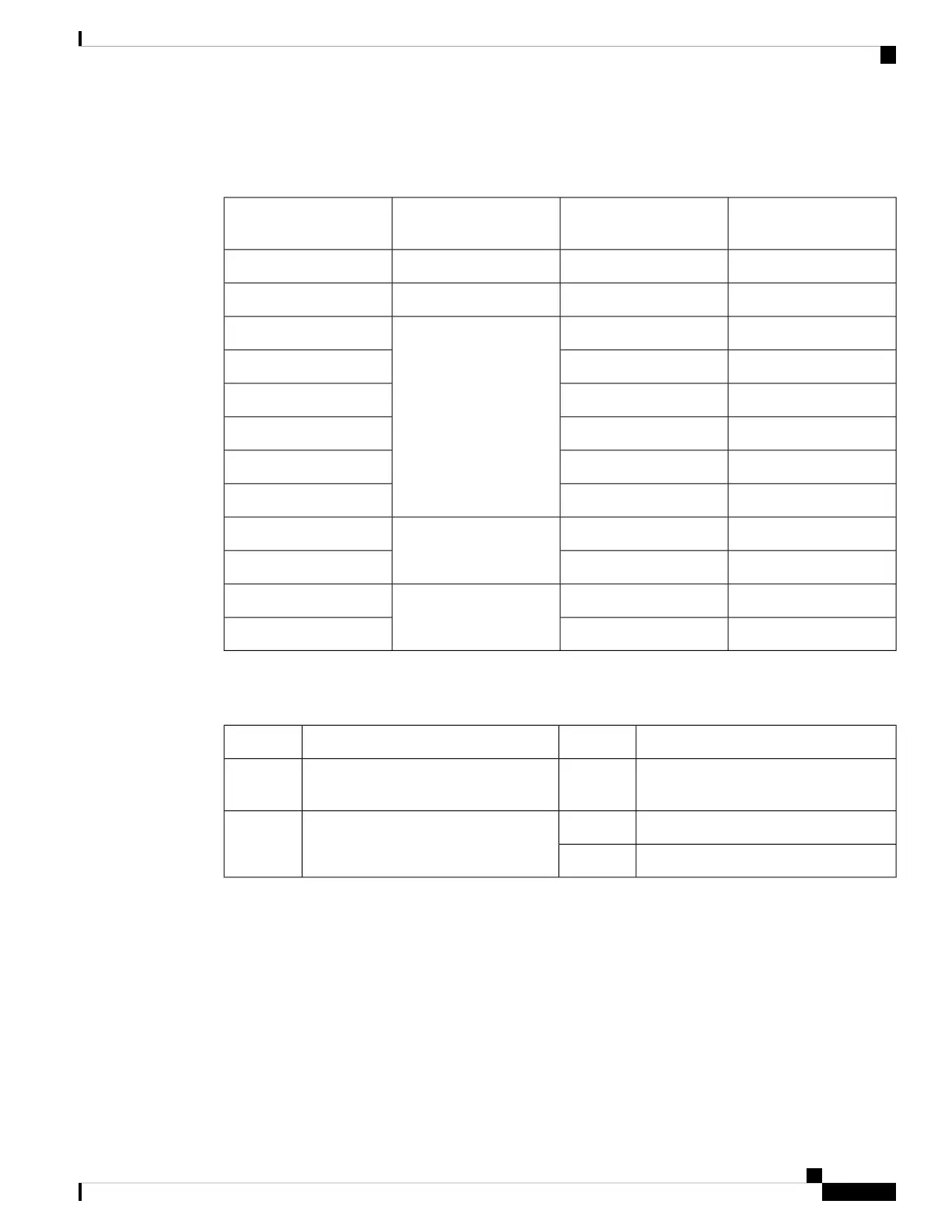
The following tables show the PoE available and PoE requirements for PoE switch models.
Table 4: Available PoE with AC Power Supply
Full PoE with Redundant
Power Supply
Available PoEDefault Power SupplyModels
740W370WPWR-C5-600WACC9200-24P
1440W740WPWR-C5-1KWACC9200-48P
——PWR-C5-125WACC9200-24T
——C9200-48T
——C9200L-24T-4G
——C9200L-24T-4X
——C9200L-48T-4G
——C9200L-48T-4X
740W
370WPWR-C5-600WACC9200L-24P-4G
740W370WC9200L-24P-4X
1440W
740WPWR-C5-1KWACC9200L-48P-4G
1440W740WC9200L-48P-4X
The power supply modules have two status LEDs.
Table 5: Switch Power Supply Module LEDs
DescriptionPS OKDescriptionAC OK
Output is disabled, or input is outside
operating range (AC LED is off).
OffNo AC input power.Off
Power output to switch active.GreenAC input power present.Green
Output has failed.Red
Fan Modules
The Cisco Catalyst 9200 Series Switches supports two internal fixed 12-V fan modules and two field-replaceable
fan modules (C9200-FAN=). The C9200 models support modular fans whereas the C9200L models provide
two internal fixed fans.
For information about the type of fan module supported on different switch models, see Switch Models, on
page 1.
Cisco Catalyst 9200 Series Switches Hardware Installation Guide
9
Product Overview
Fan Modules
 Loading...