• To prevent ESD damage, follow your normal board and component handling procedures when connecting
cables to the switch and other devices.
• When you insert several SFP/SFP+ modules in multiple switch ports, wait for 5 seconds between inserting
each SFP/SFP+. This will prevent the ports from going into error disabled mode. Similarly, when you
remove an SFP/SFP+ from a port, wait for 5 seconds before reinserting it.
Procedure
Step 1 Attach an ESD-preventive wrist strap to your wrist and to an earth ground surface.
Step 2 Find the send (TX) and receive (RX) markings that identify the top of the SFP/SFP+ module.
On some SFP/SFP+ modules, the send and receive (TX and RX) markings might be shown by arrows that
show the direction of the connection.
Step 3 If the SFP/SFP+ module has a bale-clasp latch, move it to the open, unlocked position.
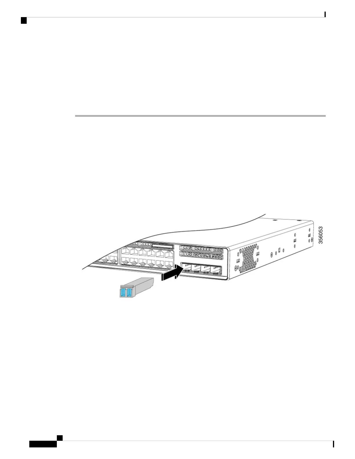
Step 4 Align the module in front of the slot opening, and push until you feel the connector snap into place.
Figure 23: Installing an SFP Module in the Network Module
Step 5 If the module has a bale-clasp latch, close it to lock the SFP/SFP+ module in place.
Step 6 Remove the SFP/SFP+ dust plugs and save.
Step 7 Connect the SFP/SFP+ cables.
Cisco Catalyst 9200 Series Switches Hardware Installation Guide
36
Installing a Network Module
Installing SFP/SFP+ Modules
 Loading...