14
Cisco Catalyst 9120AX Series Access Points
Deploying the Access Point on the Wireless Network
After you have mounted the access point, follow these steps to deploy it on the wireless network:
Step 1 Connect and power up the access point.
Step 2 Observe the access point LED (for LED descriptions, see “Checking the Access Point LEDs” section on
page 14).
a. When you power up the access point, it begins a power-up sequence that you can verify by observing the
access point LED. If the power-up sequence is successful, the discovery and join process begins. During this
process, the LED blinks sequentially green, red, and off. When the access point has joined a controller, the
LED is chirping green if no clients are associated or green if one or more clients are associated.
b. If the LED is not on, the access point is most likely not receiving power.
c. If the LED blinks sequentially for more than 5 minutes, the access point is unable to find its primary,
secondary, and tertiary Cisco Wireless Controller. Check the connection between the access point and the
Cisco Wireless Controller, and be sure the access point and the Cisco Wireless Controller are either on the
same subnet or that the access point has a route back to its primary, secondary, and tertiary Cisco Wireless
Controller. Also, if the access point is not on the same subnet as the Cisco Wireless Controller, be sure that
there is a properly configured DHCP server on the same subnet as the access point. See the “Configuring
DHCP Option 43” section on page 17 for additional information.
Step 3 Reconfigure the Cisco Wireless Controller so that it is not the master.
Note A master Cisco Wireless Controller should be used only for configuring access points and not in a
working network.
12 Checking the Access Point LEDs
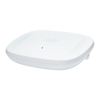
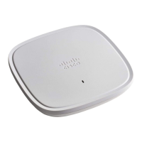
The location of the access point status LED is shown in Figure 2.
Note Regarding LED status colors, it is expected that there will be small variations in color intensity and hue from
unit to unit. This is within the normal range of the LED manufacturer’s specifications and is not a defect.
However, the intensity of the LED can be changed through the controller.
The access point status LED indicates various conditions and are described in Table 2.
Table 2 LED Status Indications
Message Type LED State Message Meaning
Association status Green Normal operating condition, but no
wireless client associated
Blue Normal operating condition, at least one
wireless client association
Boot loader status Green Executing boot loader
Boot loader error Blinking Green Boot loader signing verification failure
 Loading...

