Ultimate disposal of this product should be handled according to all national laws and regulations.
Statement 1040
Warning
Identifying Switching Module Slots
The slot numbers on the fan tray front panel help you easily identify the switching module slots or the non-supervisor slots. Install
switching modules only in these slots.
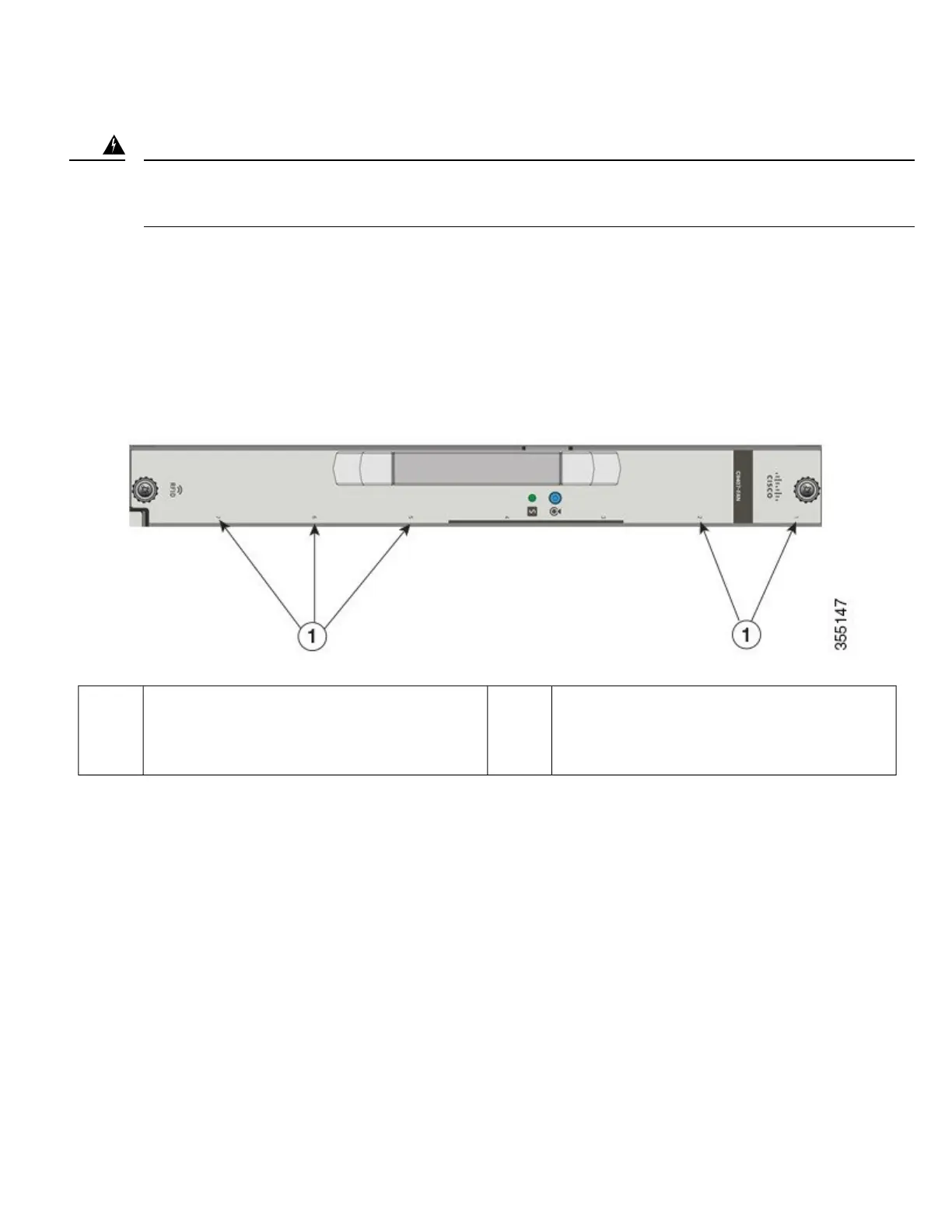
Figure 9: Switching Module Slot Numbers on the Fan Tray's Front Panel
The following figure shows the switching module slots in a Catalyst 9407R Switch, where the fan tray model number is C9407-FAN.
Fan tray assemblies are chassis-specific and other chassis fan tray front panels have similar numbering that indicates the switching
module slots available on the corresponding
chassis.
--Switching module slots numbered 1, 2, 5, 6, and 7.
Supervisor module slots are indicated by a
vertical bar in additional to the slot number.
Note
1
Required Tools
You will need these tools to install or remove supervisor modules and switching modules
• Your own ESD-prevention equipment or the disposable grounding wrist strap included with all upgrade kits, field-replaceable
units (FRUs), and spares.
• Antistatic mat or antistatic bag
• Number 1 and number 2 Phillips screwdrivers for the captive installation screws on most modules
• 3/16-inch flat-blade screwdriver for the captive installation screws on some modules
23
 Loading...