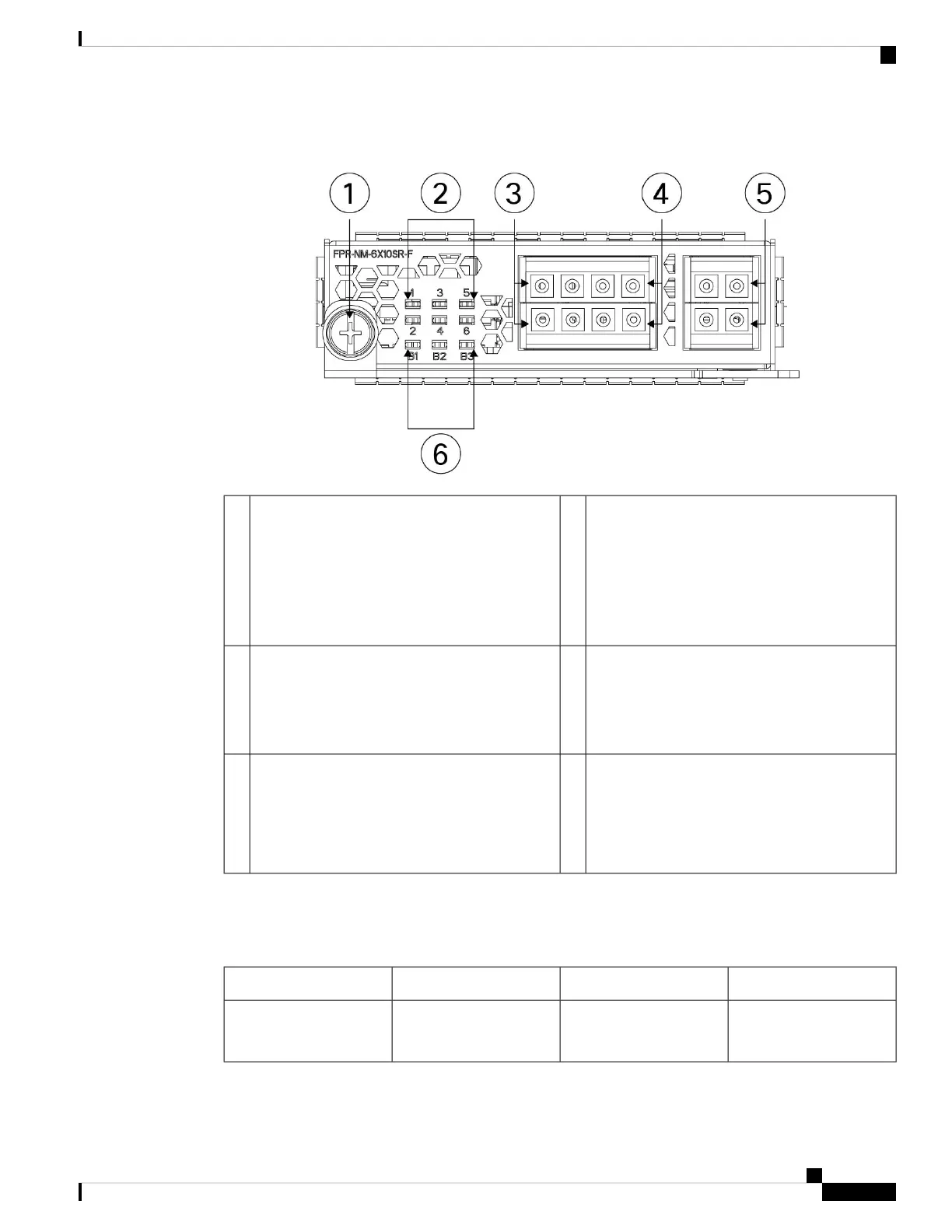
Figure 14: FPR4K-NM-6X1SX-F, FPR4K-NM-6X10SR-F, FPR4K-NM-6X10LR-F
Six network activity LEDs:
• Amber—No connection, or port is not in use,
or no link or network failure.
• Green—Link up, no network activity.
• Green, flashing—Network activity.
2Captive screw/handle1
Ethernet X/3 (top port)
Ethernet X/4 (bottom port)
Ports 3 and 4 are paired together to form a
hardware bypass pair.
4Ethernet X/1 (top port)
Ethernet X/2 (bottom port)
Ports 1 and 2 are paired together to form a
hardware bypass pair.
3
Bypass LEDs B1 through B3:
• Green—In standby mode.
• Amber, flashing—Port is in hardware bypass
mode, failure event.
6Ethernet X/5 (top port)
Ethernet X/6 (bottom port)
Ports 5 and 6 are paired together to form a
hardware bypass pair.
5
The 1-Gb SX /10-Gb SR/10-Gb LR network modules have the following insertion loss measurements. Insertion
loss measurements help you to troubleshoot the network by verifying cable installation and performance.
Table 4: 1-Gb SX Network Module (FPR4K-NM-6X1SX-F)
MaximumTypicalOperating Mode
1.4 dB
1.7 dB
0.9 dB
1.2 dB
Normal
Hardware bypass
Insertion loss
Overview
21
Overview
1-Gb SX/10-Gb SR/10-Gb LR Network Module with Hardware Bypass
 Loading...


