The fan modules are numbered left to right, for example, FAN1, FAN2, FAN3, FAN4, FAN5, and FAN6.
See Remove and Replace the Fan Module for the procedure for removing and replacing the fan module.
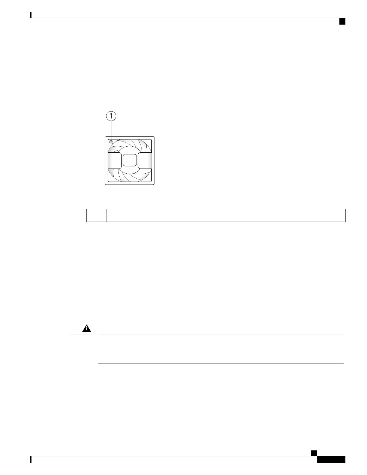
The following figure shows the location of the fan LED.
Figure 15: Fan LED
Two-color LED1
The fan module has one two-color LED, which is located on the upper left corner of the fan.
• Amber—Fan failure.
• Green—Fan running normally. It may take up to one minute for the LED status to turn green after power
is on.
Supported SFP/SFP+ and QSFP Transceivers
The SFP/SFP+ transceivers are bidirectional devices with a transmitter and receiver in the same physical
package. It is a hot-swappable optical or electrical (copper) interface that plugs into the SFP/SFP+ ports on
the fixed ports and the network module ports, and provides Ethernet connectivity.
Use appropriate ESD procedures when inserting the transceiver. Avoid touching the contacts at the rear,
and keep the contacts and ports free of dust and dirt. Keep unused transceivers in the ESD packing that
they were shipped in. The following figure shows a sample SFP transceiver.
Warning
Overview
25
Overview
Supported SFP/SFP+ and QSFP Transceivers
 Loading...


