Front Panel
The following figure shows the front panel of the Firepower 4100.
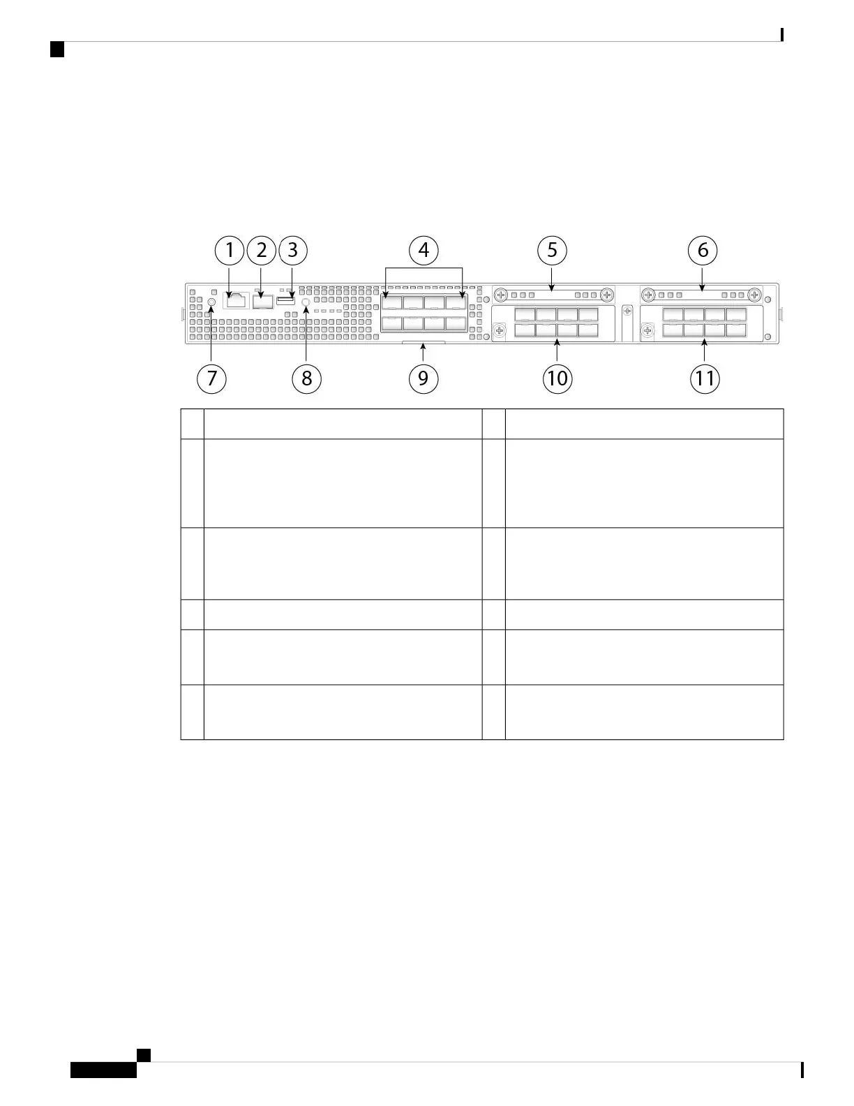
Figure 5: Firepower 4100 Front Panel
Gigabit Ethernet management port2RJ-45 console port1
Eight fixed SFP+ (1-Gb/10-Gb) ports (in network
module slot 1)
Ethernet 1/1 through 1/8 labeled top to bottom,
left to right
4USB 2.0 Type A port3
SSD 2
Reserved for the optional MSP.
6SSD 1
Reserved for the primary SSD; slot 1 must always
be populated.
5
Locator LED8Power LED7
Network module 2
The 10-Gb network module is shown.
Note
10Pullout asset card9
Network module 3
The 10-Gb network module is shown.
Note
11
RJ-45 Console Port
The Firepower 4100 has a standard RJ-45 console port. You can use the CLI to configure your Firepower
4100 through the RJ-45 serial console port by using a terminal server or a terminal emulation program
on a computer.
The RJ-45 (8P8C) port supports RS-232 signaling to an internal UART controller. The console port does
not have any hardware flow control, and does not support a remote dial-in modem. The baud rate is 9600.
You can use the standard cable found in your accessory kit to convert the RJ-45 to DB-9 if necessary.
Type A USB Port
You can use the external USB Type A port to attach a data storage device. The external USB drive
identifier is disk1:. The USB Type A port supports the following:
• Hot swapping
Overview
8
Overview
Front Panel
 Loading...


