5
Make sure the PC interface connected to the PIX 501 inside port, numbered 1 through 4, is set to
autonegotiate for best performance. If autonegotiate is not an option for the PC interface, set the speed
to either 10 or 100 Mbps half duplex. Setting the interface to full duplex causes a duplex mismatch that
significantly impacts the total throughput capabilities of the interface.
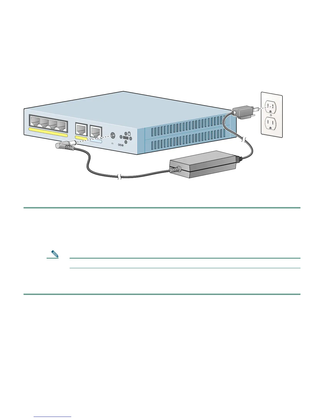
Follow these steps to power on the PIX Firewall:
Step 1 Connect the power supply (341-0008-01) with the power cable (72-0259).
Step 2 Connect the small, round connector of the power supply cable to the power connector on the
rear panel.
Step 3 Connect the AC power connector of the power supply input cable to an electrical outlet.
Note The PIX 501 does not have a power switch. Completing Step 3 powers on the device.
Step 4 Check the power LED, if it is solid green, then the device is powered on. For more
information, refer to the “Check the LEDs” section on page 12.
P
O
W
E
R
4
3
2
1
0
CONSOLE
3
.3
V
4
.5
A
71331
Power supply
Cisco PIX 501
 Loading...