- 3 -
PP-2449H
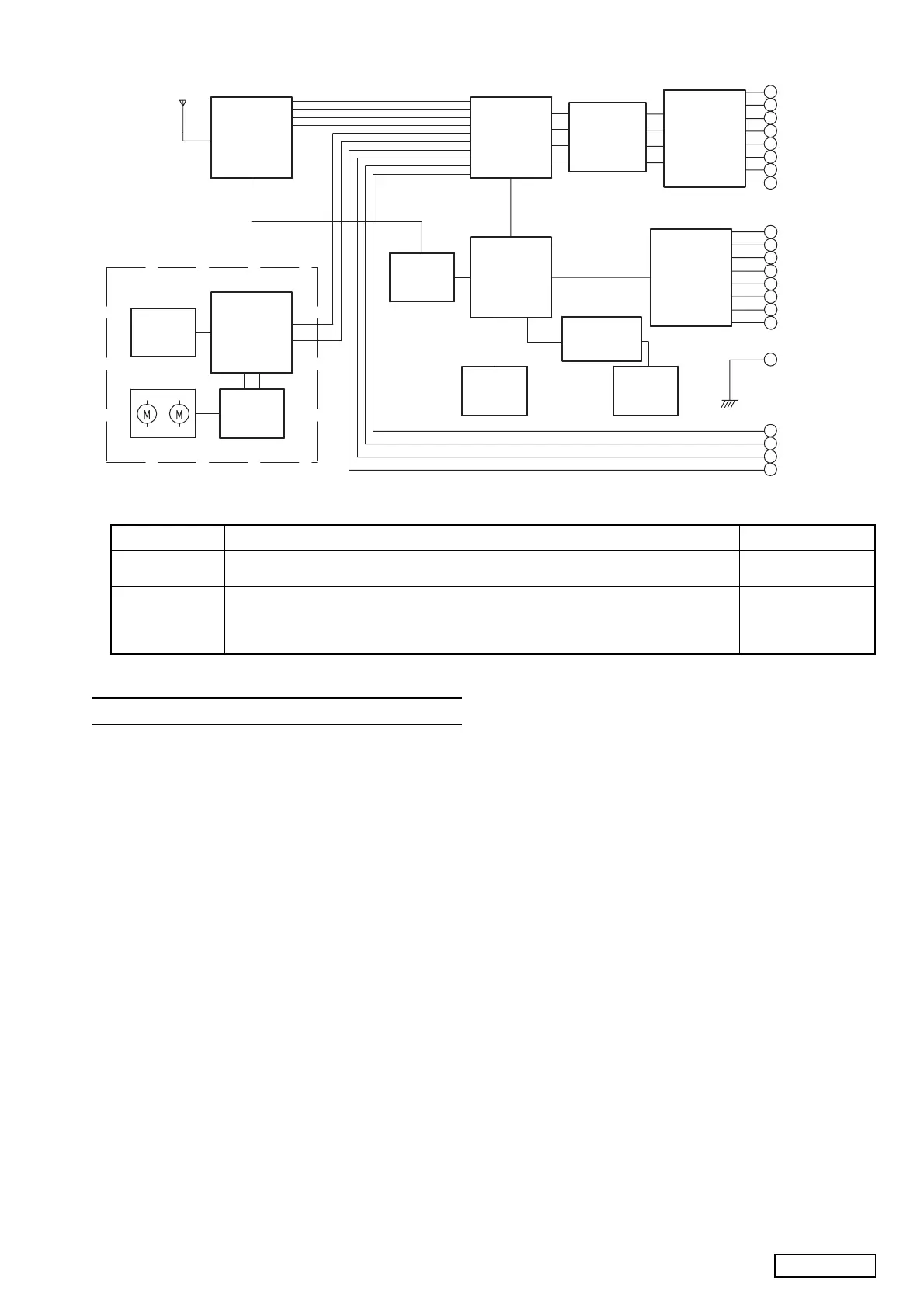
■BLOCK DIAGRAM
8 8 0 - 1 9 1 7 B
A M / F M T U N E R
I C 3 0 2
L C 7 5 3 8 6
E L E C T R O N I C
V O L U M E
I C 5 0 1 - 5 0 5
N J M 2 0 6 0
E Q U A L I Z E R
P P - 2 4 4 9 H - B : N O N F A D E R
I C 5 0 6
T D A 7 5 6 0
P O W E R I C
P O W E R
S U P P L Y
C D M E C H A N I S M
T A 2 1 5 7 F
R F A M P
T C 9 4 A 1 4 F A
D S P
M O T O R
D R I V E R
B A 5 9 8 3 F P
L P F
I C 2 0 1
u P D 1 7 8 0 7 6 G F
R A D I O / C D
C O N T R O L L E R
K E Y
M A T R I X
& S W I T C H
L C D
I C 9 0 1
L C 7 5 8 5 3
L C D D R I V E R
A
O
B
L
E
N
F
P
G
H
I
C
D
2
1
K
J
6
4
5
7
A N T
N C
B A C K U P
I L L . C O N T
I L L U M I N A T I O N
A C C
F L S P +
R L S P +
F R S P +
R R S P +
F L S P -
R L S P -
F R S P -
R R S P -
N C
O N - S I G N A L I N
O N - S I G N A L O U T
G N D
L -
L +
R +
R -
■ADJUSTMENT
Noise
convergence
Clock accuracy
1. Input a 98.1MHz/55dB(1kHz,30% MOD)signal.(0dB=1.4V)
2. Adjust the output to
−18±3dB by VR102 when the SSG output is set −20dBμ.
1. Turn off and on the ACC switch,while holding CD EJECT button and POWER
button.Repeat it twice slowly.
2. Set a universal timer to TP201,adjust TC201 so that a reading of the meter is
0
±0.1 sec/day.
SSG
Milli-volt meter
Universal timer
Item Procedure
Measuring
instrument
■EXPLANATION OF IC
052-1173-00 uPD178076GF-541-3BA Radio & CD Controller
1.Terminal Description
pin 1: EJECT SW_ : IN : The eject key signal input.
pin 2: NU : - : Not in use.
pin 3: NU : - : Not in use.
pin 4: VOL DATA : O : Serial data output to the electric volume IC.
pin 5: VOL CLOCK : O : Serial data clock output to the electric vol-
ume IC.
pin 6: VOL CE : O : Chip enable signal output to the volume IC.
pin 7: NU : - : Not in use.
pin 8: LCD DI_ : IN : Serial data input from the LCD driver.
pin 9: LCD DO : O : Serial data output to the LCD driver.
pin 10: LCD CLK : O : Serial data clock output to LCD driver.
pin 11: LCD CE : O : Chip enable signal output to the LCD driv-
er.
pin 12: NU : - : Not in use.
pin 13: POWER SW_ : IN : Power switch pulse input.
pin 14: VOL 1 : IN : Volume control pulse input from the rotary
switch.
pin 15: VOL 2 : IN : Volume control pulse input from the rotary
switch.
pin 16: ILL_ : IN : Illumination ON signal input.
pin 17: NU : - : Not in use.
pin 18: NU : - : Not in use.
pin 19: NU : - : Not in use.
pin 20: NU : - : Not in use.
pin 21: NU : - : Not in use.
pin 22: NU : - : Not in use.
pin 23: NU : - : Not in use.
pin 24: NU : - : Not in use.
pin 25: NU : - : Not in use.
pin 26: NU : - : Not in use.
pin 27: A VDD : - : Positive supply voltage for the Analog sec-
tion.
pin 28: NU : - : Not in use.
pin 29: NU : - : Not in use.
pin 30: NU : - : Not in use.
pin 31: NU : - : Not in use.
pin 32: A VSS : - : Analog ground.
pin 33: REG CPU : IN : Capacitor connection terminal to suppress
the ripple.
pin 34: VDD 0 : - : Positive supply voltage.
pin 35: REG OSC : IN : Capacitor connection terminal to suppress
the ripple.
pin 36: X 2 : - : Crystal connection.
pin 37: X 1 : - : Crystal connection.
pin 38: GND 0 : - : Ground.
pin 39: NU : - : Not in use.
pin 40: GND 2 : - : Ground.
pin 41: AM IF :IN : Input terminal of the internal universal
counter for AM IF.
pin 42: FM IF :IN: Input terminal of the internal universal
counter for FM IF.
pin 43: VDD PLL : - : Positive supply voltage for the PLL.
pin 44: FM OSC : IN : Input terminal of the internal counter for FM
OSC( Local Oscillation ).
pin 45: AM OSC : IN : Input terminal of the internal counter for AM
OSC( Local Oscillation ).
pin 46: GND PLL : - : Ground for the PLL.
pin 47: Voltage Tune : O : PLL error output.
pin 48: NU : - : Not in use.
pin 49: IC : IN : Not in use.
pin 50: RESET_ : IN : Reset signal input.
pin 51: SP INIT : IN : 4SP = "L" , 2SP = "H".
pin 52: NU : - : Not in use.
pin 53: ST_/TWEET_ :I/O: Outputs "L" at AM 900kHz receiving. Inputs
"L" at FM stereo receiving.
pin 54: CLK INT :IN : Without the clock display = "H".
pin 55: AUX ON_ : IN : AUX ON signal input.
pin 56: TEST : IN : Test enable signal input.
pin 57: LCD ON_ : O : LCD back light ON signal output.
 Loading...