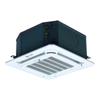
27
Configuration
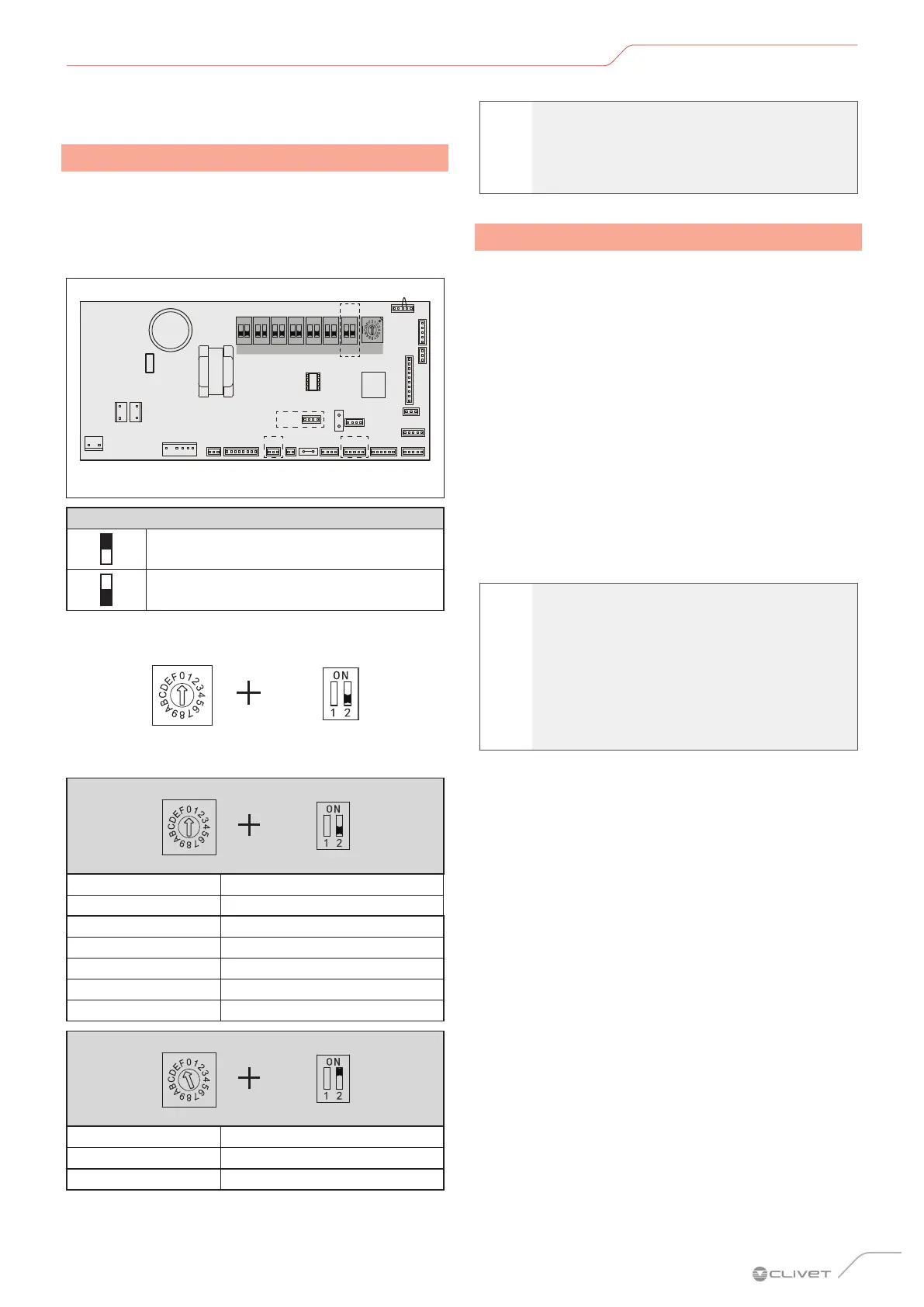
4 CONFIGURATION
4.1 Power setting
Set the board’s DIP switch on the internal electrical panel
for different applications. Once it has been set, disconnect
the main power switch and then reconnect it.
If the main switch is not disconnected and then
reconnected, the setting will not be applied.
CN17
CN20
CN21
CN5CN25
CN31
CN30
J1
CN14
CN16J2
CN11CN6CN4
CN24
CN2
CN3 CN13
CN7 CN8
CN55
CN9
CN15
Main control panel
ENC1
SW1 SW7SW2SW3SW4SW5
SW6
ONON
POWER_S
ONONONONON
ON
1 2
ON
1 2
ON
1 2
ON
1 2
ON
1 2
ON
1 2
ON
1 2
Fig. 37
Key
Dip-switch ON (1)
Dip-switch OFF (0)
SW7
ENC1 Power DIP Switch settings:
SW7
Toggle switch Set cooling capacity
Dial code Cooling capacity
0 2200 W
1 2800 W
2 3600 W
3 4500 W
4 5200 W
SW7
Toggle switch Set cooling capacity
Dial code Cooling capacity
F 1700 W
l
WARNING
The power DIP switches have been configured
before delivery. These settings must only be
changed by qualified maintenance personnel.
4.2 Address setting
When the indoor unit is connected to the outdoor unit,
the outdoor unit will automatically distribute the address
to the indoor unit. Or the controller can be used to set the
address manually.
– Indoor units can have the same address in the
same system.
– The network address and the indoor unit address
are the same and do not have to be configured
separately.
– Once the address settings have been completed,
mark the address on each indoor unit to facilitate
after-sales maintenance.
– The centralised controller for the indoor unit is
completed on the outdoor unit. For further details,
refer to the outdoor unit manual.
a
CAUTION
Once the indoor unit has completed the
centralised control function on the outdoor
unit, the DIP switch on the main control panel
of the outdoor unit must be set to auto-
addressing; otherwise the indoor units in the
system are not controlled by the centralised
controller.
– The system can connect up to 64 indoor units
(0~63 addresses) simultaneously. Units with the
same address can cause a malfunction
 Loading...