assembly
/
10. Remove the headstock pulley-using the 5/32" set-
screwwrench.
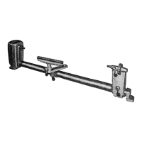
11: Find four pan head thread cutting screws 3/8" long
and four Iockwashers from among the loose parts.
Attach the belt guard with these screwsand Iockwash-
er_ The arrows in this illustration show the location of
the screws.
°i
/
/
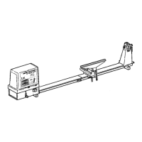
12, Place the t_eadstock pulley onto the headstock shaft as
shown. Position it so that the end of the put|ey is flush
with the end of the lathe spindle.
13. Place the motor pulley on the motor shaft so that the
small diameter is approximately 1/16" away from the
motor.
14. NmOoToEr:shWhf_n_1_s_l _tgrteh_hPa_It_/eO_/;65fS"_lud_ra_n_tee;
furnished with your motor is in place. Then tighten the
setscrew with a 5/32" setscrew wrench.
/
/
/
/
/
3/16 x 3/16 KEY
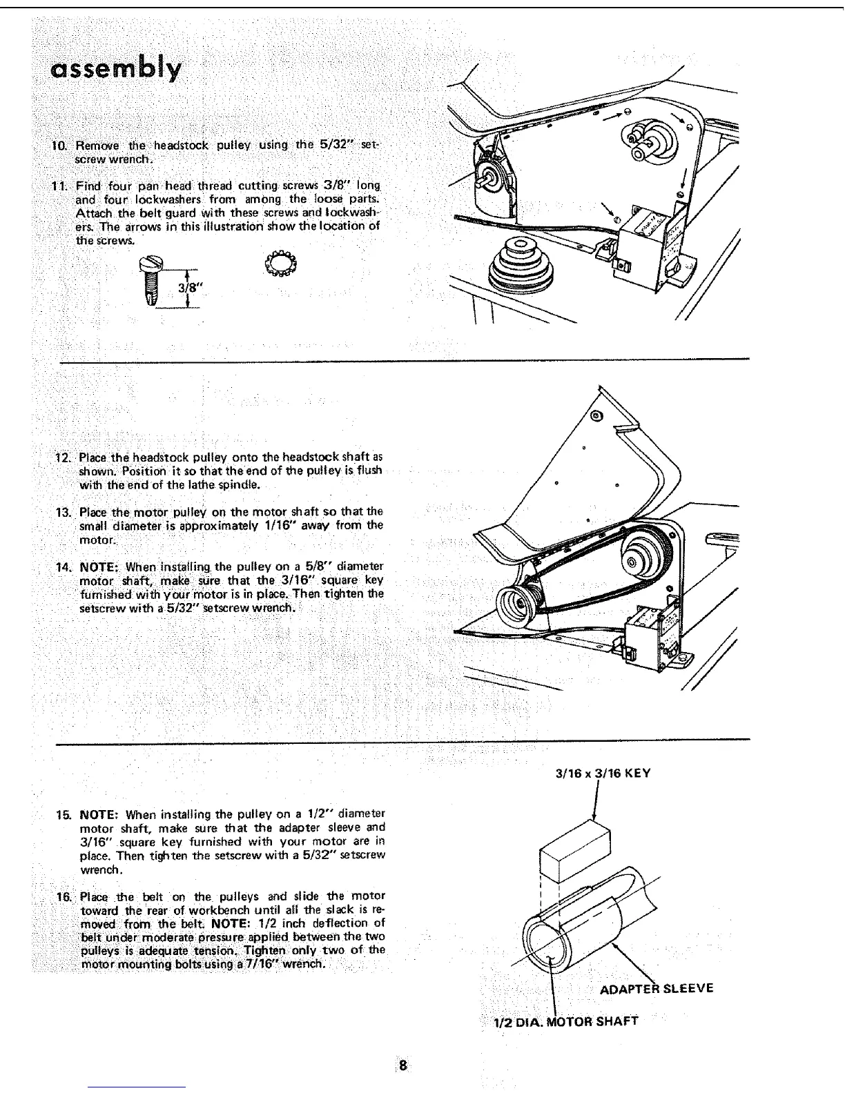
15. NOTE: When installing the pulley on a 112" diameter
motor shaft, make sure that the adapter sleeve and
3/I6" square key furnished with your motor are in
place. Then tighten the setscrew with a 5/32" setscrew
wrench,
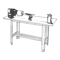
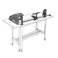
16, Place the belt on the pulleys and slide the motor
toward the rear of workbench until al_lthe slack is re*
moved from the belt. NOTE: 1/2 inch deflection of
belt under moderate pressure,applied between the two
pulleys is adequate :tenSion, Tighten only two of the
motor mounting boltsusing a7/16 wrench.
ADAPTER SLEEVE
T
1/2 DIA. MOTOR SHAF
 Loading...