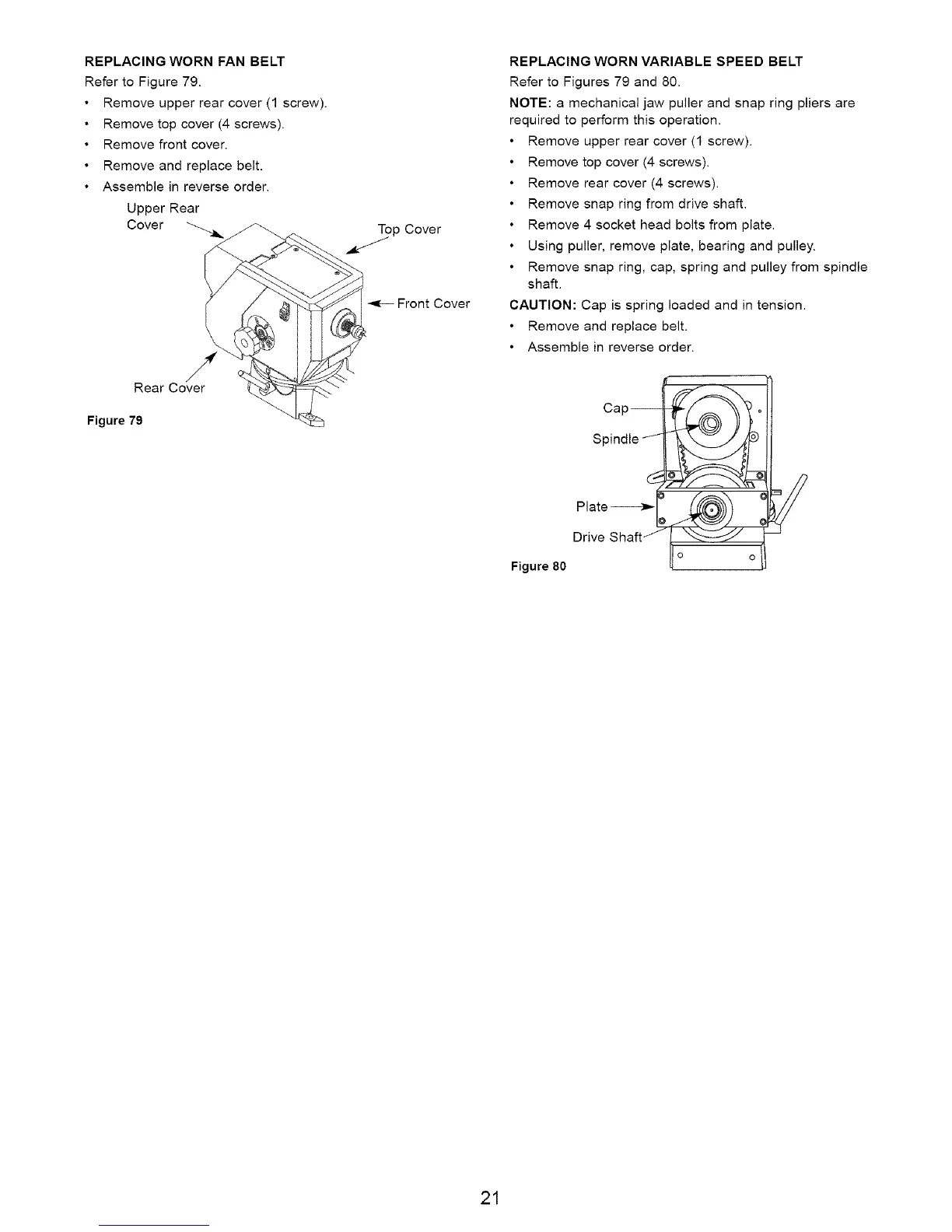
REPLACING WORN FAN BELT
Refer to Figure 79.
Remove upper rear cover (1 screw).
Remove top cover (4 screws).
Remove front cover.
Remove and replace belt.
• Assemble in reverse order.
Upper Rear
Cover
Rear Cover
Figure 79
Top Cover
Front Cover
REPLACING WORN VARIABLE SPEED BELT
Refer to Figures 79 and 80.
NOTE: a mechanical jaw puller and snap ring pliers are
required to perform this operation.
Remove upper rear cover (1 screw).
Remove top cover (4 screws).
Remove rear cover (4 screws).
Remove snap ring from drive shaft.
Remove 4 socket head bolts from plate.
Using puller, remove plate, bearing and pulley.
Remove snap ring, cap, spring and pulley from spindle
shaft.
CAUTION: Cap is spring loaded and in tension.
Remove and replace belt.
Assemble in reverse order.
Figure 80
Cao
Spindle _
21
 Loading...