TOASSEMBLETHEHANDLEAND
CRANKASSEMBLY
1. Cuttieholdingshiftrodtolower
handleandmoveshiftertothefirst
forwardgear.
2. Cutanddiscardtheplastictiethat
securesthecrankassembly.
3. Loosen,butdonotremove,the
screws,flatwashers,Iockwashers,
andhexnutsintheupperholesof
thelowerhandle.SeeFigure3.
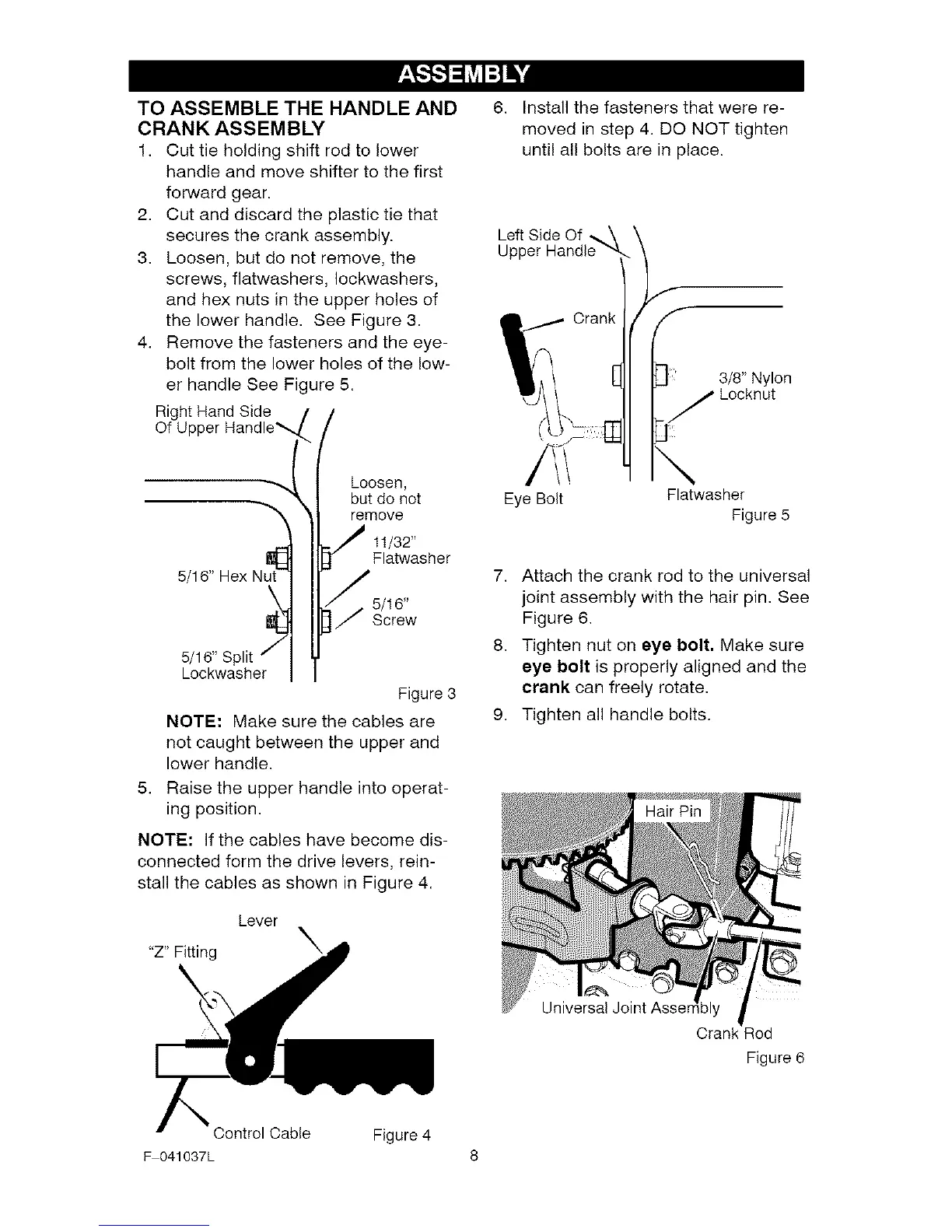
4. Removethefastenersandtheeye-
bolt from the lower holes of the low-
er handle See Figure 5.
RightHand Side
Of Upper Handle%
Loosen,
but do not
remove
11/32"
EF{
Flatwasher
5/16" Hex Nut'_;;t
5/16"
Screw
5/16" Split
Lockwasher
Figure 3
NOTE: Make sure the cables are
not caught between the upper and
lower handle.
5. Raise the upper handle into operat-
ing position.
NOTE: if the cables have become dis-
connected form the drive levers, rein-
stall the cables as shown in Figure 4.
Lever
"Z" Fitting X
6. Install the fasteners that were re-
moved in step 4. DO NOT tighten
until all bolts are in place.
Left Side Of _.\
Upper Handle --4.
Crank
Eye Bolt
f
3/8" Nylon
Locknut
j!i!
\
Flatwasher
Figure 5
7. Attach the crank rod to the universal
joint assembly with the hair pin. See
Figure 6.
8. Tighten nut on eye bolt, Make sure
eye bolt is properly aligned and the
crank can freely rotate.
9. Tighten all handle bolts.
Universal Joint Asser
Crank Rod
Figure 6
Control Cable Figure 4
F 041037L 8
 Loading...