14
DIODE TEST
WARNING: To avoid electric shock, do not test any diode that
has voltage on it.
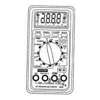
1. Turn the rotary switch to the •))) CAP position.
2. Insert the black test lead banana plug into the negative (COM)
jack and the red test lead banana plug into the positive (V
jack.
3. Push the mode button to indicate on the display.
4. Touch the test probes to the diode under test. Typically for a
normal diode, forward voltage will indicate 0.4V to 0.7V.
Reverse voltage will indicate “OL”. Shorted devices will
indicate near 0V and an open device will indicate “OL” in both
polarities.
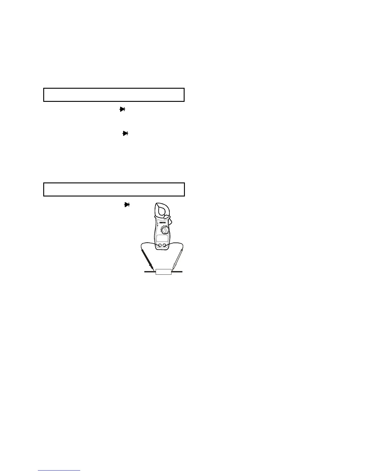
CAPACITANCE MEASUREMENTS
WARNING: To avoid electric shock, discharge the capacitor
under test before measuring.
1. Set the function switch to the
•))) CAP position.
2. Push the mode button to indicate nF
on the display.
3. Insert the black lead banana plug into
the negative (COM) jack and
insert the red test lead banana plug
into the positive (VTemp) jack.
4. Press the ZERO key to null the meter
display.
5. Touch the test probe tips to the
capacitor you wish to check.
6. Read the capacitance value on the
display.
 Loading...