13
ENGLISH
Operating the Pruner (Fig.A)
WARNING: Read and understand all instructions.
Failure to follow all instructions listed below may result
in electric shock, fire and/or serious personalinjury.
• Guard Against Kickback which can result in severe
injury or death. See Important Safety Instructions
Guard Against Kickback, to avoid the risk
ofkickback.
Installing and Removing the Battery Pack
(Fig.O)
WARNING: Ensure the tool/appliance is in the off
position before inserting the batterypack.
NOTE: For best results, make sure your battery pack is
fullycharged.
1. To install the battery pack
12
into the tool handle, align
the battery pack with the rails inside the tool’s handle
and slide it into the handle until the battery pack is firmly
seated in the tool and ensure that it does notdisengage.
2. To remove the battery pack from the tool, press the
release button
16
and firmly pull the battery pack out of
the tool handle. Insert it into the charger as described in
the charger section of thismanual.
NOTE: DO NOT hold the saw by the front hand guard
3
.
Proper hand position requires the left hand on the front
handle
14
, under the front hand guard
3
, with the right
hand on the rear handle
13
.
Proper Hand Position (Fig.N)
WARNING: To reduce the risk of serious personal injury,
ALWAYS use proper hand position asshown.
WARNING: To reduce the risk of serious personal
injury, ALWAYS hold securely in anticipation of a
suddenreaction.
OPERATION
WARNING: To reduce the risk of serious personal
injury, turn unit off and remove the battery pack
before making any adjustments or removing/
installing attachments or accessories. An
accidental start‑up can causeinjury.
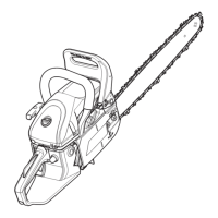
Transporting Pruner (Fig.A)
• Always turn unit off, remove the battery and cover the
guide bar
4
with the scabbard
10
when transporting
thepruner.
Bar Tip Guard (Fig.A)
WARNING: Never operate the pruner without the
bar tip guard properly mounted on the guide bar
to prevent rotational kickback.
The bar tip guard
6
reduces the chance of the chain
5
at
the end of the guide bar
4
from coming into contact with
objects which may cause the bar and chain to kickback
towards the operator. In addition to reducing the chance of
kickback, the bar tip guard
6
will reduce the chance of the
chain from touching the ground.
Scabbard and Wrench Storage (Fig.L, M)
The scabbard
11
has two functions, to cover the guide bar
4
when the tool is not in use and to store the wrench
12
.
Scabbard
1. To open the scabbard , lift up on the latch
20
and pull
the two halves apart.
2. To close the scabbard, close the two halves and ensure
the latch is secured to the notch
21
.
Wrench
1. Open the scabbard to gain access to the wrench.
2. Remove the wrench by lifting the wrench end up and
away from the scabbard.
3. Store the wrench in the scabbard when finished. First
install flat screwdriver end of the wrench into the retaining
slot
22
and then press the wrench end down until the
retaining clips
23
firmly secure the wrench in place.
Replacement chain and bar are available from your
nearest authorized servicecenter.
The CMCCS320 requires replacement 6"(152mm) chain
CMZCSC06
. Replacement 6" (152mm) barCMZCSB06.
Replacing the Saw Chain (Fig.F - I)
WARNING: Sharp moving chain. To prevent accidental
operation, ensure that battery is removed from the tool
before performing the following operations. Failure to
do this could result in serious personalinjury.
CAUTION: Sharp chain. Always wear protective gloves
when handling the chain. The chain is sharp and can
cut you when it is notrunning.
CAUTION: The chain speed of this product is 4.4 m/s.
Only use chains that are rated at greater than 4.4 m/s.
1. Place the saw on a flat, firmsurface.
2. Remove sprocket cover
8
as described in Installing the
Guide Bar and Saw Chainsection.
3. To remove the saw chain
5
, rotate the chain tension
screw
10
in the front of the housing using the flat
screwdriver end of the wrench. Turning the screw
counterclockwise allows the guide bar
4
to recede
and reduces the tension on the chain so that it may
beremoved.
4. Wearing protective gloves, grasp the saw chain and lift
the worn saw chain out of the groove in the guidebar.
5. Ensure guide bar is installed with the bar tip guard
6
positioned as shown in Fig.I.
6. Place the new chain in the slot of the guide bar, making
sure the saw teeth are facing the correct direction by
matching the arrow and graphic of the saw chain on the
sprocket cover
8
shown in Fig.I.
7. Follow instructions for Installing the Guide Bar and
SawChain.
2. Lubricate the whole saw chain evenly before each
use as shown in FigureK. Also lubricate the saw chain
whenever replacing a fully discharged battery with a fully
chargedone.
 Loading...