DO GUIDE
3. Carefully tighten the four screws in each corner of the assembly clockwise until the FT2-MECH assembly is secured in place against the table. Do
not overtighten the screws.
DO Install the Modules
Positioning the Modules
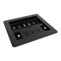
Once the FT2-MECH assembly has been mounted, install modules, blank plates, and keystone plates into the assembly as required by the FlipTop™ system.
The FT2-MECH ships with four blank connector plates and eight cable management modules. (Keystone plates must be ordered separately.) For more
information on installing specic modules, refer to the documents listed in the following table at www.crestron.com/manuals.
NOTE: The FT2A-CBLR-GR and FT2A-CP modules are compatible with the FT2-MECH; however, the LEDs on the front of these modules only light if the
FT2-MECH is tted with a power bus. The FT2A-CHGR-USBA/C module and the FT2A-CBLR-1T modules are only compatible with the FT2-ELEC or an
FT2-MECH tted with a power bus.
The following points must be observed when positioning modules in the FT2-MECH assembly:
• Install FT2A-CBLR-GR modules before installing any other modules. Next, install FT2A-PWR modules, and then install the remaining modules or
plates.
• FT2A-CBLR-GR modules can only be placed at the ends of a module row.
• Dress all cables after installing each module, and secure the cables to the bottom of the FT2-MECH assembly using the attached cable
management bar.
Installing Pass-Through Modules
Use the following procedure to install the included pass-through cable modules in the FT2-ELEC assembly. Each pass-through cable module is packaged
with one grommet and one cable plate. One empty module space is required for installation.
1. Pull the grommet apart, and insert the cable inside so that the connector is above the grommet. Then, press the grommet back together to secure
the cable inside.
2. Push the grommet with the cable into the cable plate until it is secured.
FT2-MECH Series
FlipTop™ FT2 Series, Mechanical
DO Check for Obstructions
The Crestron
®
FT2-MECH is designed to install into a table or other horizontal surface. Before cutting the mounting hole, check underneath the table for
any obstructions that would impede the installation of the FT2-MECH assembly, retractors, and accessories. Refer to the dimensions in the illustrations and
bulleted notes below.
• Retractors must occupy either of the two ends of a module row and can mount only to the sides of the FT2-MECH assembly.
• FT2A-CBLR-GR retractors extend from the FT2-MECH assembly 20.86” (530 mm) vertically and 1.55” (39 mm) horizontally underneath the table.
• FT2A-CBLR-1T retractors extend from the FT2-MECH assembly 4.33” (110 mm) vertically and 8.23” (209 mm) horizontally underneath the table.
• FT2A-UTK-SHELF shelves can mount to any side of the FT2-MECH assembly and extend from the assembly 9.95” (253 mm) horizontally
underneath the table.
• FT2A-UTK-PWS power supplies can mount to any side of the FT2-MECH assembly and extend from the assembly 0.80” (20 mm) horizontally
underneath the table.
DO Mount the Assembly
Use the following procedure to mount the FT2-ELEC assembly.
1. Trace an outline of the mounting hole directly onto the table using the included cutout template. Then, have the mounting hole cut in the table with
an appropriate saw (not included).
2. Ensure that all four swiveling dogs are positioned inside of the assembly, and then insert the assembly into the mounting hole until the top lip of the
assembly is ush with the table surface. Refer to the following illustration to orient the assembly in the mounting hole.
CAUTION: Set the screwdriver torque to its lowest possible setting to avoid stripping the swiveling dogs and damaging the table. If removing the
assembly from the table, ensure that the screwdriver rotation is correctly set before untightening the screws.
DO Check the Box
QUANTITY PRODUCT COLOR PART NUMBER
3 Bars, Locking, with Screws 4527272
4 Cover, Plastic, Blank 2049602
8 Module, Cable Management 4526880
1 Template, Cutout 4527491
FT2-700-MECH-AL Only
1 Bezel, FT2-700 Alloy 4527016
FT2-700-MECH-B Only
1 Bezel, FT2-700 Black 4526341
FT2A MODULE DOCUMENT
FT2A-CBLR-GR Series Doc. 8221
FT2A-CP Series Doc. 8223
FT2A-PWR-US Series Doc. 8218
FT2-MECH
assembly
Retractable lid
(in rear of
assembly)
Swiveling dogs (4)
FT2-MECH
assembly
FT2-MECH
assembly
(overhead view)
9.95 in
253 mm
FT2A-UTK-SHELF
FT2A-CBLR-1T
retractor
8.23 in
209 mm
0.80 in
20 mm
1.55 in
39 mm
FT2A-UTK-PWS
power supply
FT2A-CBLR-GR
retractor
FT2-MECH
assembly
(overhead view)