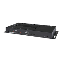
Observe the following when connecting the control system:
l The control system is powered over PoE (Power over Ethernet)via a
Crestron PoEinjector (PWE-4803RU) or a Crestron PoEswitch
(CEN-SW-POE-5 or CEN-SWPOE-16). All PoEequipment is sold
separately.
l The included cables may not be extended.
l Mount the included antenna per the guidelines described in Mount the
Antenna.
l Connect the chassis ground lug to a known earth ground circuit (such
as building steel) to ensure that the control system is grounded
properly.
l Apply power after all connections have been made.
Mount the Antenna
The included antenna should be placed in a location that maximizes signal
strength and limits impedance. Refer to the Best Practices for Installation
and Setup of Crestron RFProducts (Doc. 6689) at
www.crestron.com/manuals.
If installing the control system in a rack enclosure, the antenna should be
mounted outside of the enclosure using the Crestron ANT-EXT-10 (sold
separately). For more information, refer to the ANT-EXT-10 Installation
Guide (Doc. 7047) at www.crestron.com/manuals.
Configure the Device
The control system may be configured using the provided web
configuration interface. The interface can be accessed using the control
system IP address or the Crestron XiOCloud™ service.
Configuration via IP Address
To access the web configuration interface using the control system
IPaddress:
NOTE:The control system ships with DHCPenabled. A DHCPserver is
required to access the web configuration interface via the device
IPaddress.
1. Connect the control system to the network.
2. Use the Device Discovery tool in Crestron Toolbox™ software to
discover the control system and its IP address on the network.
3. Enter the control system IPaddress into a web browser.
MC4/MC4-I
Quick Start
4

 Loading...