Page 35
Contractor Series Power Amplifiers
Reference Manual
BLOWER
(OPTION 2)
BLOWER
(OPTION 1)
AIR
FLOW
FRONT
OF
RACK
DOOR
AIR
FLOW
EQUIPMENT
RACK
(SIDE VIEW)
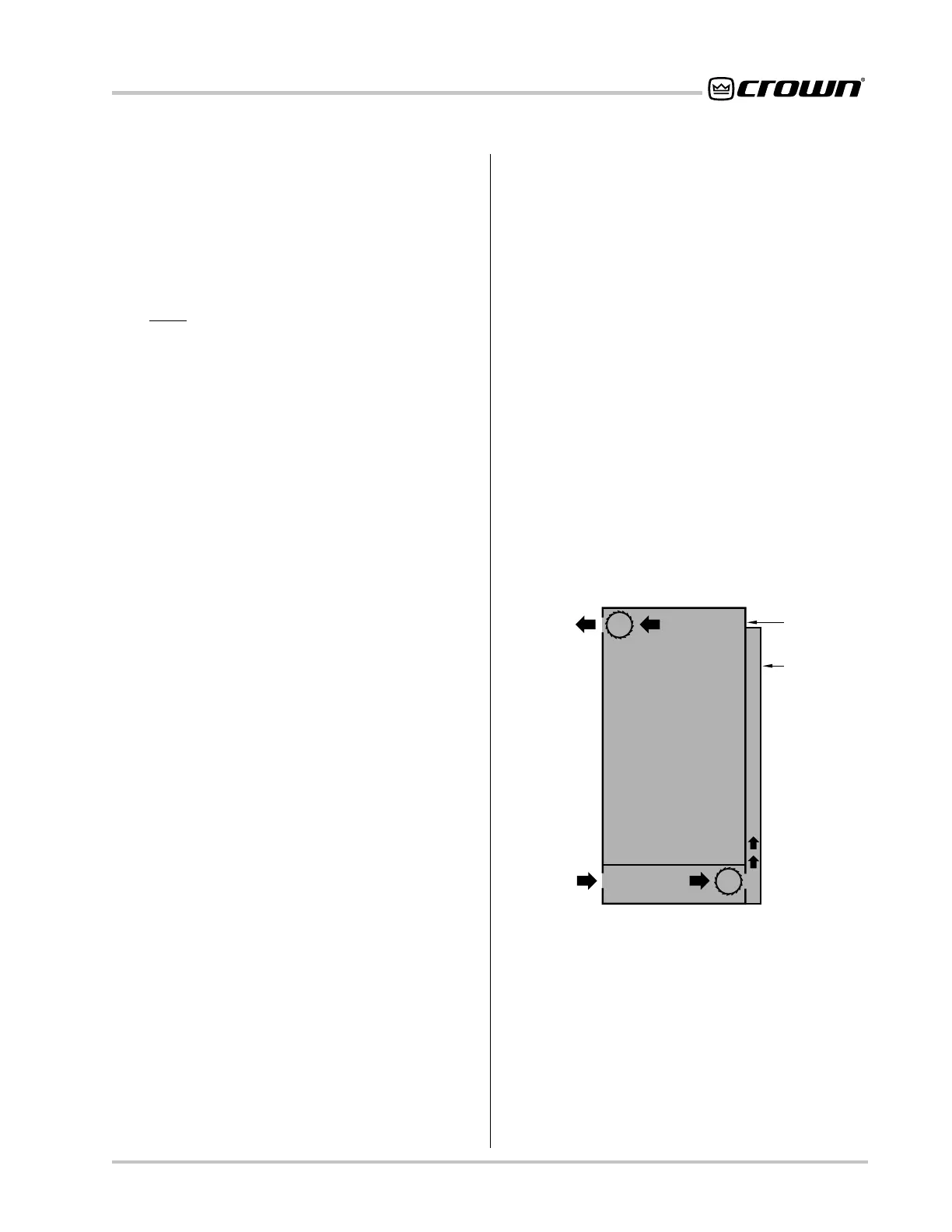
Figure 9.1 Extra Cooling with a Rack-Mounted Blower
9 Installation Helps
9.1 Cooling
It is important to understand cooling considerations
when installing a Contractor Series amplifier. Proper
cooling of your amplifier will ensure efficient uninter-
rupted operation even under varying conditions.
First,
never block the amplifier’s front or rear air vents.
This can cause poor air flow and may result in overheat-
ing. Many things can cause air flow restrictions, includ-
ing improper mounting, bunched up power cords,
closed rack doors, and clogged intakes and/or exaust
vents. A Contractor Series amplifier should be mounted
in a way that allows sufficient air flow into the front in-
takes, out the rear exhaust vents, and out the back of
the rack. Open spaces in the front of the rack should be
covered with blank panels to prevent heated air from
the rear exhaust vents from being drawn into the front
air intake which may greatly reduce the cooling system’s
effectiveness.
The air flow requirement for a Contractor Series ampli-
fier depends on many things, but the most important
factor is average output power. Air flow requirements
increase as output power increases, so anything that
affects output power also affects the required air flow.
Average output power is mainly affected by three
things: (1) duty cycle of the input signal, (2) load im-
pedance, and (3) rated output power. First, as the duty
cycle of the input signal increases, the average output
power level increases. For example, the amplifier will
need more air flow with a rock ‘n’ roll input signal than
with infrequent paging. Second, as the load impedance
of a connected loudspeaker gets smaller, more current
will flow through the load which effectively increases
output power. This means you can expect the amplifier
to require more air flow with a 2-ohm load than with an
8-ohm load. Finally, an amplifier that is rated for higher
power output is usually used at higher average output
levels. So for example, a CL2 delivering full output will
require more air flow than a CL1.
9.1.1 Additional Cooling
If multiple amplifiers will be operated under demanding
conditions (such as driving loads less than 4 ohms), or
if air flow through the rack will be restricted, you should
verify that the total air flow through the rack will be suffi-
cient. Cooling can be improved by reducing air restric-
tions, installing a rack-mounted blower, or using an air
conditioner.
If your rack has a front door, it is usually best to leave it
open and avoid blocking the air intakes. If this is impos-
sible, supplement the air flow by mounting a grille in the
door or using a rack-mounted blower. If you install a
grille in the door, we recommend wire grilles instead of
perforated panels, because wire tends to cause less air
restriction (perforated panels cause a minimum air re-
striction of 40%). If rack will be located in a dusty or
dirty environment, it is advisable to pre-filter the air us-
ing industrial furnace filters. These filters can be taped
or fastened to the front of the equipment rack, ensuring
a clean air supply through a large surface area that will
require minimum maintenance.
A better choice for increasing the air flow behind a rack
cabinet door is to use a “squirrel cage” blower. Mount
the blower at the bottom of the rack so it blows outside
air into the space between the door and the front of the
amplifiers, pressurizing the “chimney” behind the door
(Figure 9.1, Option 1). The blower should not blow air
into or take air out of the space behind the amplifiers.
For racks without a front door, you can evacuate the
rack by mounting the blower at the top of the rack so
that air blows out the back (Figure 9.1, Option 2).
9.2 Input Wiring
A balanced audio circuit typically will have both posi-
tive (+) and negative (–) legs of the circuit isolated from
the ground circuit. These balanced legs exhibit identi-
cal impedance characteristics with respect to ground,
and may also carry the audio signal at the same level,
but with opposite polarities. This results in a line that
offers excellent rejection of unwanted noise.
On the other hand, an unbalanced circuit usually holds
 Loading...