LPS Series Power Amplifiers
Operation Manual
page 4
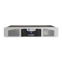
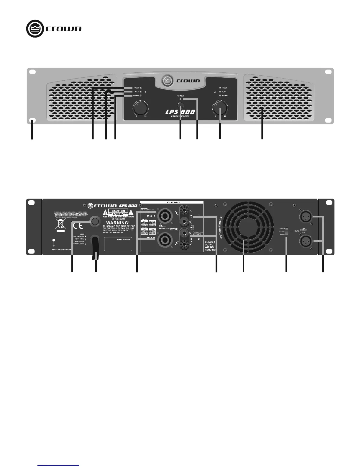
Front Panel
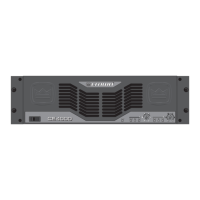
Back Panel
FRONT PANEL
1. Rack-mount hole (one of four)
2. Fault LED: Red LED, one per channel, indicates channel
shutdown.
3. Clip LED: Red LED, one per channel, flashes when signal is
audibly distorting.
4. Signal Presence LED: Green LED, one per channel,
flashes when input signal exceeds -40 dBu.
5. Power Switch: Push-on, push-off.
6. Power LED: Blue LED illuminates when amplifier is on.
7. Volume Control: Sets output level of each channel.
8. Grille: Allows flow-through ventilation from front to back.
BACK PANEL
9. Reset Button: Resets the circuit breaker.
10. Power Cable: Permanently attached cable connects to AC
mains power.
11. Output Connectors: One Speakon
®
per channel connects to
loudspeakers.
12. Output Connectors: One pair binding posts per channel
connects to loudspeakers.
13. Grille: Allows flow-through ventilation from front to back.
14. Output Mode Switch: Stereo (dual), Parallel or Bridge.
15. Input Connectors: Balanced XLR, one per channel.
Figure 2. Back Panel Controls and Connectors
Figure 1. Front Panel Controls and Indicators
10
11
9
13
12
14 15
1
3
2
4
5
6
7
8
 Loading...