39
B. DECK LEVELING ADJUSTMENTS
In order to achieve even cutting, the mower deck must
be properly leveled. This leveling procedure will result
in the left and right blades having corresponding
cutting-edge-to ground measurements within 1/16 inch
of each other. Also, the blades will each have a 1/8 to
1/4 inch downward tilt toward the front of the tractor. To
level the mower deck, proceed as follows:
WARNING
Before making any adjustments, place the PTO
switch in the “OFF” position, engage the brake
pedal lock, turn the ignition key to the “OFF”
position, and remove the key from the switch.
Disconnect the spark plug wires for additional
safety. When handling the mower deck, be
careful not to cut yourself on the sharp blades.
NOTE
Check for proper tire inflation before making a
leveling adjustment. The tractor and deck
MUST be placed on a hard, level surface during
leveling adjustment.
1. Position the tractor and mower deck on a hard,
level surface.
2. The mower deck front and rear gauge wheels
should be installed in their uppermost position in
the deck brackets to prevent contact with the hard,
level surface below. Refer to GAUGE WHEEL
ADJUSTMENT.
3. Raise the tractor implement lift handle to its
highest setting.
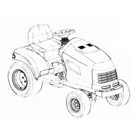
4. Carefully rotate the outer cutting blades so that
they are positioned perpendicular to the tractor
frame (See Figure 48).
Figure 48
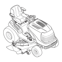
5. Referring to Figure 49, measure and record the
distance from the hard, level surface to the outer-
most cutting edge of the right blade. Repeat this
step for the left blade. If the two blade heights are
not within 1/16 inch, proceed to steps 6, 7 and 8.
If the two blade heights are within 1/16 inch,
proceed to FRONT TO BACK LEVELING
ADJUSTMENT.
Figure 49
6. Lower the deck onto the hard, level surface.
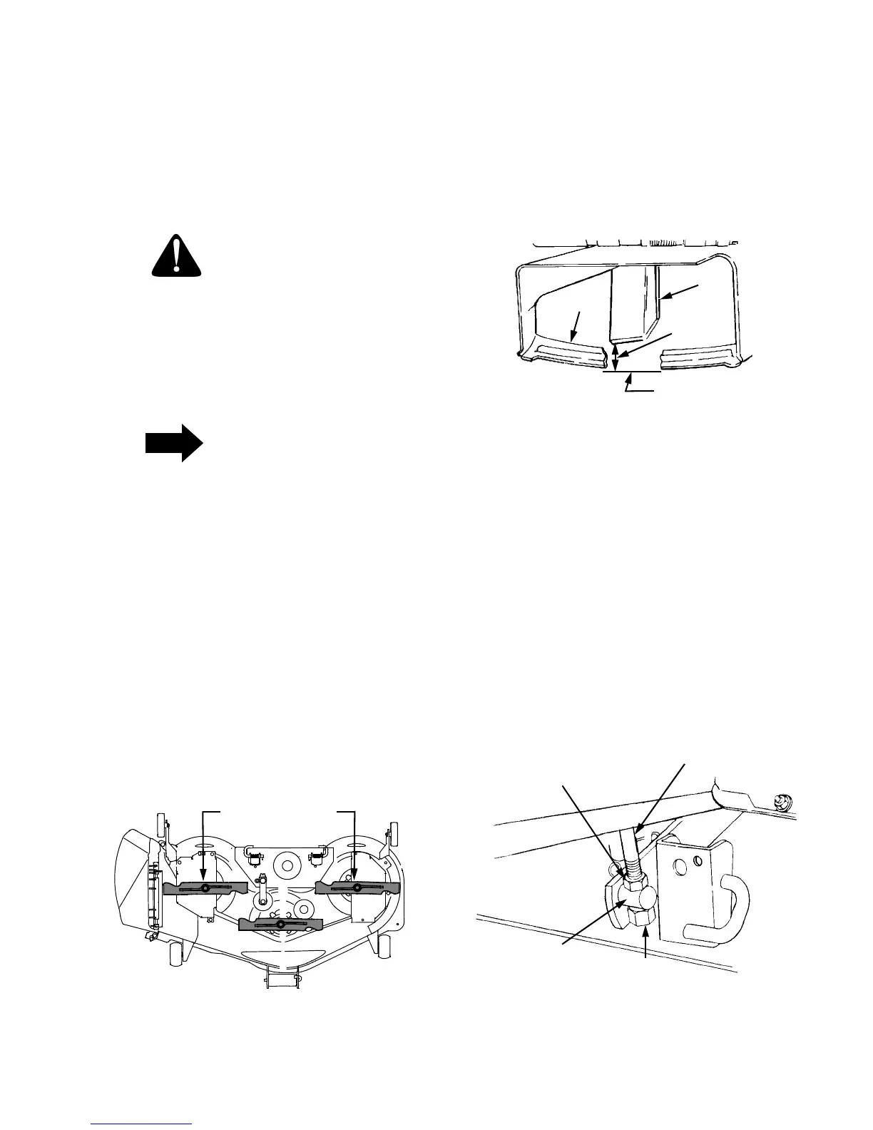
7. Side-to-side leveling is obtained utilizing the
adjustment ferrule and right hand lifty link rod
(Refer to Figure 50).
8. Loosen the upper jam nut on the lift link rod and
turn away from the adjustment ferrule. Turn the
lower lock nut upward (tighten) on the threads of
the rod to raise the right side of the mower deck.
Turn the lock nut down (loosen) on the threads to
lower the right side of the mower deck (See Figure
50).
Figure 50
OUTER BLADES
TO FRAME
PERPENDICULAR
1. Finger guard
2. Blade
3. Hard Level Surface
4. Measure This Distance
1
2
3
4
RIGHT HAND
LIFT LINK ROD
UPPER
JAM NUT
ADJUSTABLE
FERRULE
LOWER
LOCK NUT
 Loading...