STEERING-IVT
89
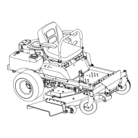
3b. Adjust the drag link until the holes line up
See Figure 6B.25.
NOTE: The punch should slide in and out with-
out binding. As the drag links are being adjusted,
rock the tires back and forth to remove the load
created from the tires twisting on the floor.
3c. Tighten the jam nuts.
4. Remove the 1/4”-20x2” screw from the steering
gear box.
5. Reinstall the original plug screw in the steering
gear box.
6. Install the steering gear covers.
7. Install the dash and fender by following the pro-
cedures described in Chapter 4: Body/Chassis.
8. Test drive the tractor in a safe area before
returning it to service.
Figure 6B.25
Rotate to lengthen or shorten
! CAUTION! CAUTION
Never allow an I-series tractor to be
operated without the steering gear
covers. Personal injury may result.
! WARNING! WARNING
Make sure all safety features are
working properly before returning
to service.
Steering gear box removal
To replace the gear box:
1. Remove the dash and fender by following the
steps described in Chapter 4: Body/Chassis.
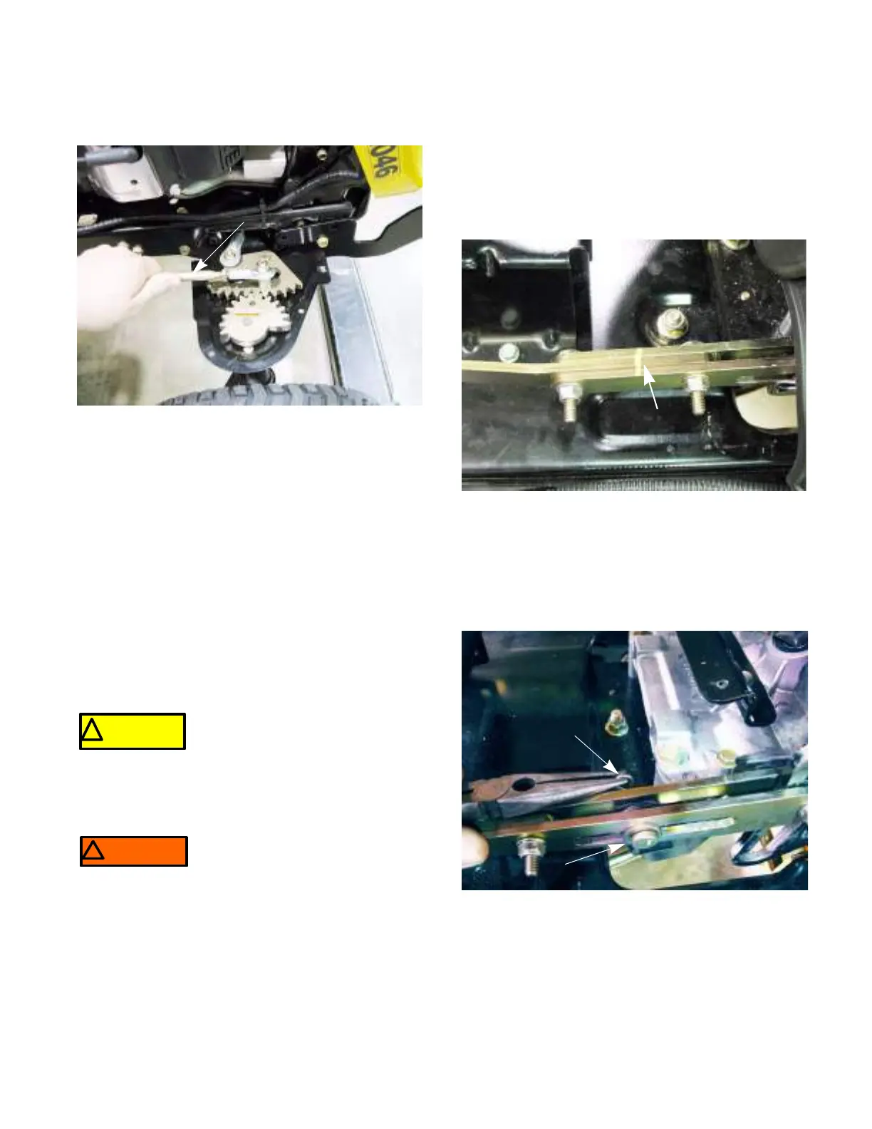
2. Match mark the drive control link between the
two nuts and bolts. See Figure 6B.26.
NOTE: The match mark will make it easier to do
the neutral adjustment later on.
3. Remove the bow tie clip and clevis pin from both
drive control links. See Figure 6B.4.
Figure 6B.26
Match mark
Figure 6B.27
bow tie clip
Clevis pin
 Loading...