9
REF NO. DESCRIPTION
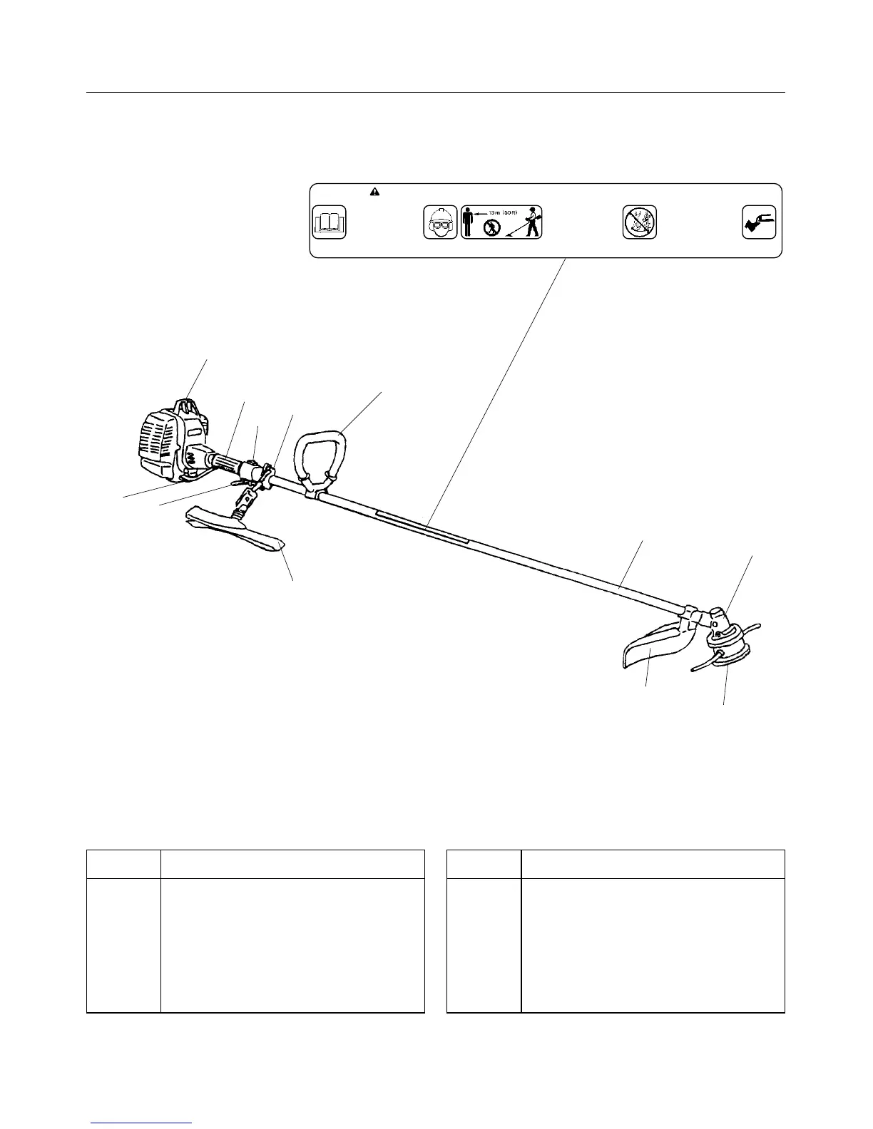
1 Gear Case
2 Grip
3 Throttle Wire
4 Throttle Lever
5 Hanger
6 Shoulder Band (Standard on ST35)
1
2
3
4
5
6
7
8
9
10
11
12
PARTS DESCRIPTION
REF NO. DESCRIPTION
7 Engine
8 Head/Blade
9 Deflector
10 Stop Switch
11 Drive Tube
12 Loop Handle
• This unit can be dangerous and cause serious
injury if improperly used. To reduce injury risk to
operator, helpers and bystanders, read and
understand the Operator and Safety Manual.
• Blindness can occur from objedts that are thrown
or ricochet even with shield in place. Operators,
helpers and bystanders must wear eye protec-
tion, ANSI Z87.1 approved.
• Always wear hearing protection when operating
unit.
• Use caution when refueling hot engine. Never
refuel while engine is on.
• Prevent accidental contact with unit and any cuting
attachment. Maintain a 50 ft. (15 m) radius,
DAN-
GER ZONE surrounding the operator. ONLY the
operator, dressed in proper protective clothing
should be in the DANGER ZONE.
• Beware of KICKOUT【blade thrust】when using
blades. Special precautions are necessary for
blade operation, see your Operator and Safety
Manual. ONLY install manufacturer approved
blades on Brushcutter models equipped with prop-
er blade shields, harness, blade collar, nut and cot-
ter pin.
• Blade/Cutting attachment does not stop immediately
after releasing throttle. Keep hands and feet clear of
blade/cutting attachment unless engine is shut off
and cutting attachment is not moving.
• INSPECT BLADES BEFORE USE.
• DO NOT USE DAMAGED, CRACKED, BENT, DULL
OR IMPROPERLY SHARPENED BLADES.
• Do not remove shields modify the unit or install
attachments or parts not approved by manufacturer.
Approved attachment information and replacement
Operator and Safety Manual are available from man-
ufacturer.
WARNING
kickout
 Loading...