®. Climbing capacity: N6 ° .
®. Minimum turning radius : 1200 mm.
⑩.Theoretical Distance: N10 km.
4.
Primary function
Stepless speed regulat ion
After the programmed speed adjustment, press forward 4 gears, back 1 gears control.
Controller overvoltage protection
Protect the controller in case of battery overpressure.
Motor blocking protection
The utility model can prevent the motor from overheat and damage when the obstacle i s blocked.
The application part is connected with the live part, and the direct current between the two parts is
W5mA.
11 can protect the circuit from over-current of itself and externa 1 power supply.
Non-insulated electrical component
protection
Ensure that the user is not exposed to non-insulated parts of the motor or burned.
The body of the chair is col 1aps i
b1e
Easy to transport and store.
Prevent wheelchairs from tipping over rough roads.
Electromagnet i c compat ibi1i ty
11 can be used normally in electromagnetic environment wi thout causing electromagnetic
disturbance to the environment.
5.
Working Environment
.Ambient temperature:-10 ° C ' 40 ° c;
.Relative humidity: 25% ~ 95% ;
.Internal power supply: DC24V.
6.
Installation and commissioning
The Electric Wheelchair has been debugged before it leaves the factory.
According to the transport requirements, part of the product factory parts used to break down packaging, so the user needs
to be simple installation before use.
.Open the electric wheelchair packing box, you can check the contents of the packing
list in the information bag.
.Pull the frame left and right to make the vehicle width normal, and press down on the
seat to make the left and right brackets into grooves.
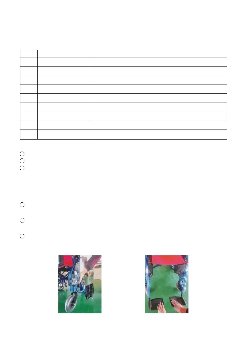
.Install the left and right foot pedal assembly, insert it down into the iron column
and turn it forward until the positioning mechanism is locked; then loosen the screws at the bottom of the Pedal
Assembly, adjust the pedal height to the proper position and re-tighten the screws (see figure below).
 Loading...