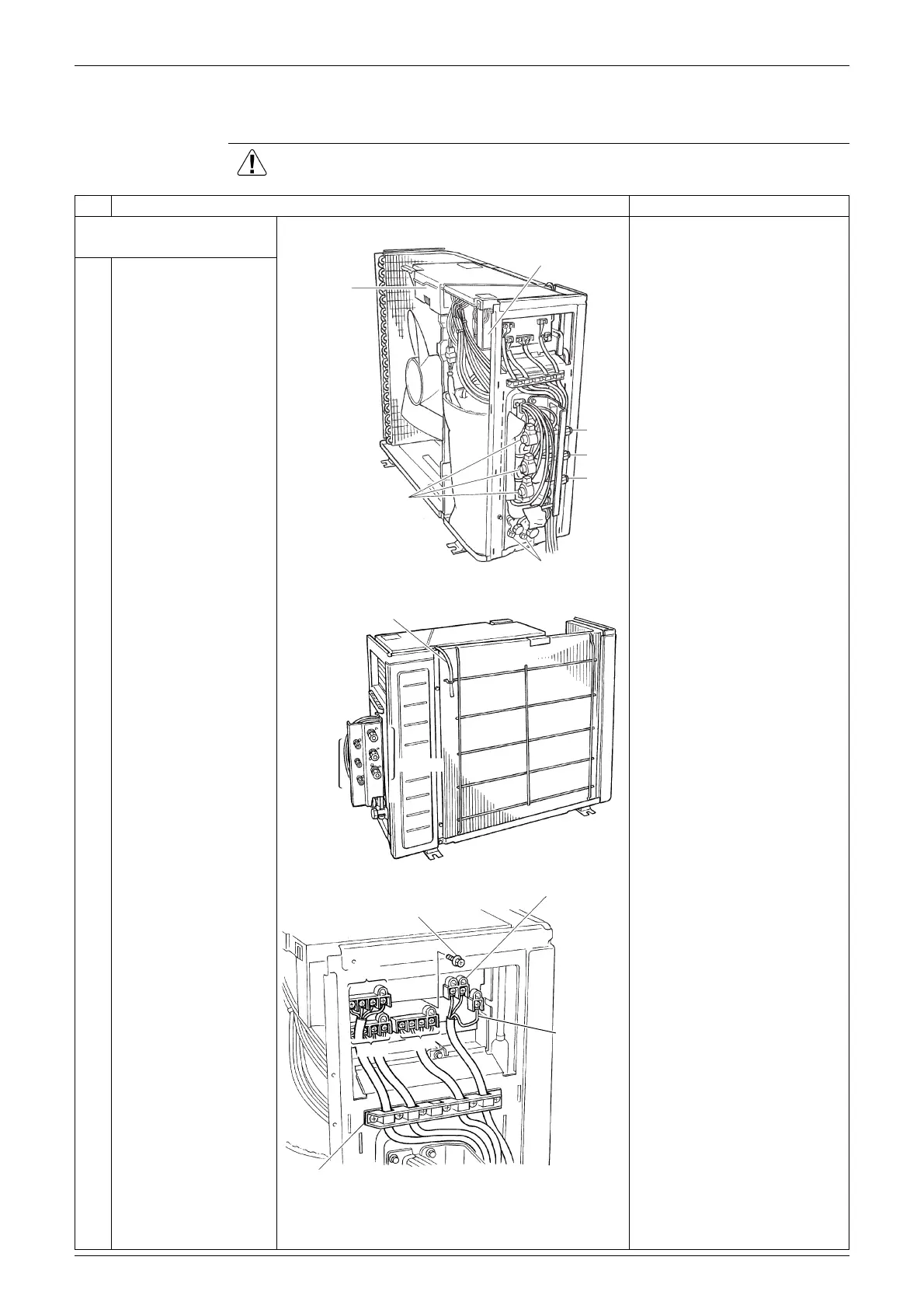
Si12-793 Removal of Electrical Box
Removal Procedure 3
2. Removal of Electrical Box
Procedure Warning Be sure to wait for 10 minutes or more after turning off all power
supplies before disassembling work.
Step
Procedure Points
1. Remove the connecting
wires.
1
The figure shows the
connecting wires.
2
Remove the terminal
board fixing screw.
Match the colors of the
connection wires to A, B and
C ports as follows.
(1) Black: Power supply
(2) White: Power supply
(3) Red: Transmission
The wires are fixed to the
terminal board with screws.
Electrical box
Electronic expansion
valve coils
Service monitor PCB
A port
B port
C port
Service port
(R3063)
Outdoor temperature thermistor
Liquid
pipe
Gas pipe
(R2163)
Terminal board fixing screw
Power supply
(L)–White
(N)–Black
A port
Earth / ground
wire
Wire fixing plate
B port
C port
(R17637)

 Loading...