9 | Electrical installation
Installer reference guide
50
4MWXM-A
R32 Split series
4P678385-1A – 2022.02
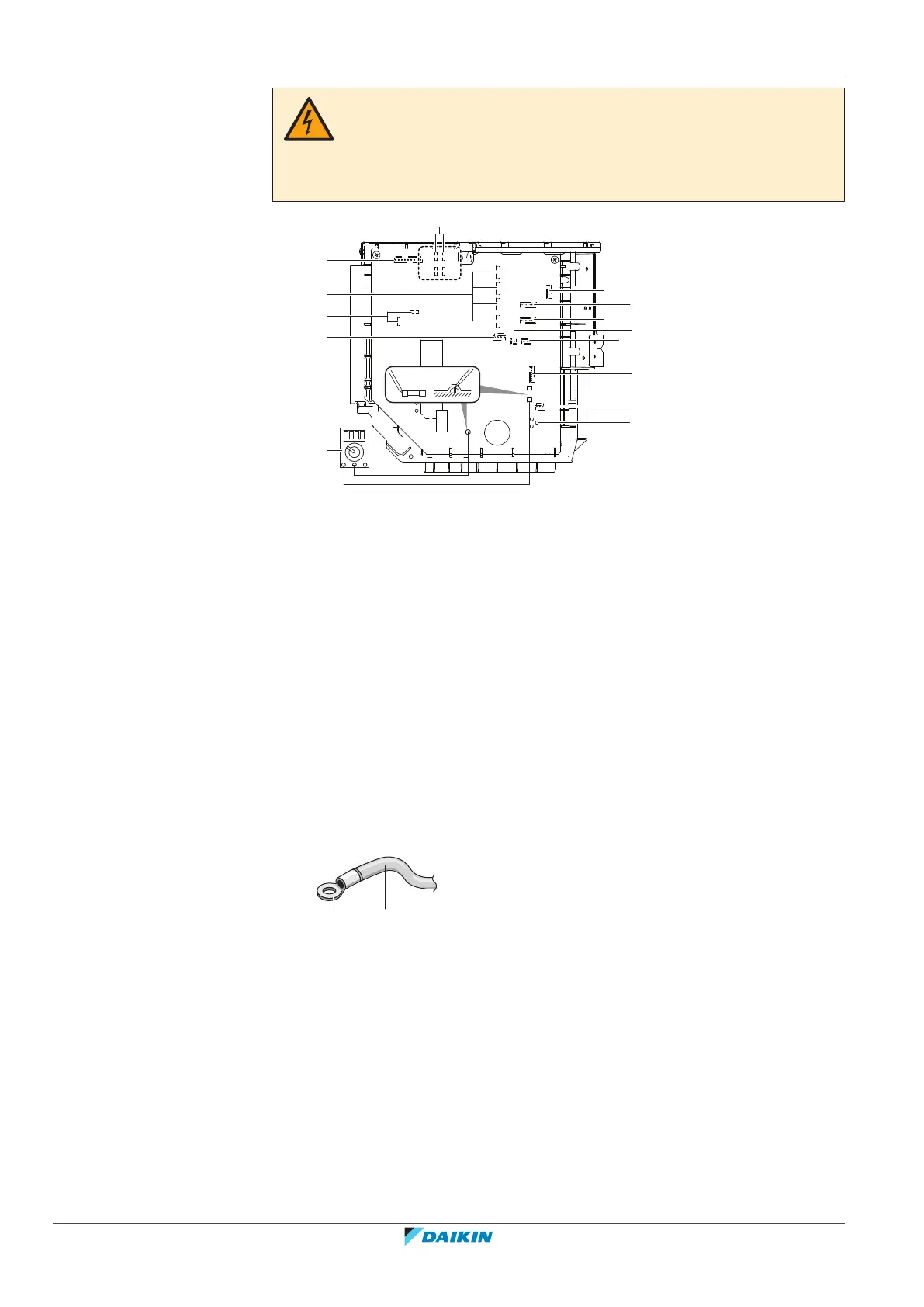
DANGER: RISK OF ELECTROCUTION
Disconnect the power supply for more than 10minutes, and measure the voltage at
the terminals of main circuit capacitors or electrical components before servicing.
The voltage MUST be less than 50VDC before you can touch electrical components.
For the location of the terminals, see the wiring diagram.
MR30_A
S80
S70
DC-
FU2
AL1
DP2 DP1
AL2
S60
S
S50
MR30_B
S20
S21
S22
S23
S93
S92
S90
W
VU
S40
ACDC
DC
c
e
d
f
b
a
l
k
j
i
g
h
DC(-)
FU2
a AL1, AL2, DP1, DP2: solenoid valve lead wire connectors
b S: terminal strip lead wire connector
c S20~S22 (room A, B, C) + S23 (TO TANK): electronic expansion valve coil lead wire
connector,
d MR30_A, MR30_B - suspend lead wire connectors
e S40: thermal overload relay lead wire and high pressure switch connector
f Multimeter (DC voltage range)
g S90, S92, S93: thermistor lead wire connector
h S50: suspend lead wire connector
i S60: pressure sensor connector
j S70: fan motor lead wire connector
k S80: 4-way valve lead wire connector
l W, V, U: Compressor lead wire connector
9.1.2 Guidelines when connecting the electrical wiring
Keep the following in mind:
▪ If stranded conductor wires are used, install a round crimp-style terminal on the
end of the wire. Place the round crimp-style terminal on the wire up to the
covered part and fasten the terminal with the appropriate tool.
a Stranded conductor wire
b Round crimp-style terminal
▪ Use the following methods for installing wires:
 Loading...