5 Piping installation
Installation manual
9
4MWXM-A9
R32 Split series
3P600450-7T – 2022.09
5.1.2 Refrigerant piping insulation
▪ Use polyethylene foam as insulation material:
▪ with a heat transfer rate between 0.041 and 0.052W/mK (0.035
and 0.045kcal/mh°C)
▪ with a heat resistance of at least 120°C
▪ Insulation thickness
Pipe outer diameter
(Ø
p
)
Insulation inner
diameter (Ø
i
)
Insulation thickness
(t)
6.4mm (1/4") 8~10mm ≥10mm
9.5mm (3/8") 12~15mm ≥13mm
12.7mm (1/2") 14~16mm ≥13mm
If the temperature is higher than 30°C and the humidity is higher
than RH80%, the thickness of the insulation materials should be at
least 20 mm to prevent condensation on the surface of the
insulation.
Use separate thermal insulation pipes for the gas and liquid
refrigerant piping.
5.1.3 Refrigerant piping length and height
difference
The shorter the refrigerant piping, the better the performance of the
system.
The piping length and height differences must comply with the
following requirements.
Shortest allowable length per room is 3m.
Refrigerant piping length to each
indoor unit
Refrigerant piping total
length
≤25m ≤50m
Height difference
outdoor-indoor
Height difference
indoor-indoor
Outdoor unit installed
higher than indoor
unit
≤15m ≤7.5m
Outdoor unit installed
lower than at least 1
indoor unit
≤7.5m ≤15m
5.2 Connecting the refrigerant piping
DANGER: RISK OF BURNING/SCALDING
CAUTION
▪ No brazing or welding on site for units with R32
refrigerant charge during shipment.
▪ During installation of the refrigeration system, joining of
parts with at least one part charged shall be performed
taking into account the following requirements: inside
occupied spaces non-permanent joints are NOT
allowed for R32 refrigerant except for site made joints
directly connecting the indoor unit to piping. Site made
joints directly connecting piping to indoor units shall be
of non-permanent type.
CAUTION
Do NOT connect the embedded branch piping and the
outdoor unit when only carrying out piping work without
connecting the indoor unit in order to add another indoor
unit later.
5.2.1 Connections between outdoor and indoor
unit using reducers
Total indoor air conditioning units capacity class that can be
connected to this outdoor unit
≤9.0kW
Port Dimensions Class Reducer
A Liquid Ø6.4mm
Gas Ø9.5mm
15, 20, 25, 35, (42)
(a)
—
B+C Liquid Ø6.4mm
Gas Ø12.7mm
15, 20, 25, 35, (42)
(a)
1+2
(accessory)
42, 50, 60 —
71
(b)
ASYCPIR
To tank Liquid Ø6.4mm
Gas Ø9.5mm
90, 120 —
(a)
Only in case of connection with FTXM42R.
(b)
Only for connection with FBA71A9. Use option ASYCPIR for
liquid (Ø9.5mm→Ø6.4mm) and gas (Ø15.9mm→Ø12.7mm)
piping.
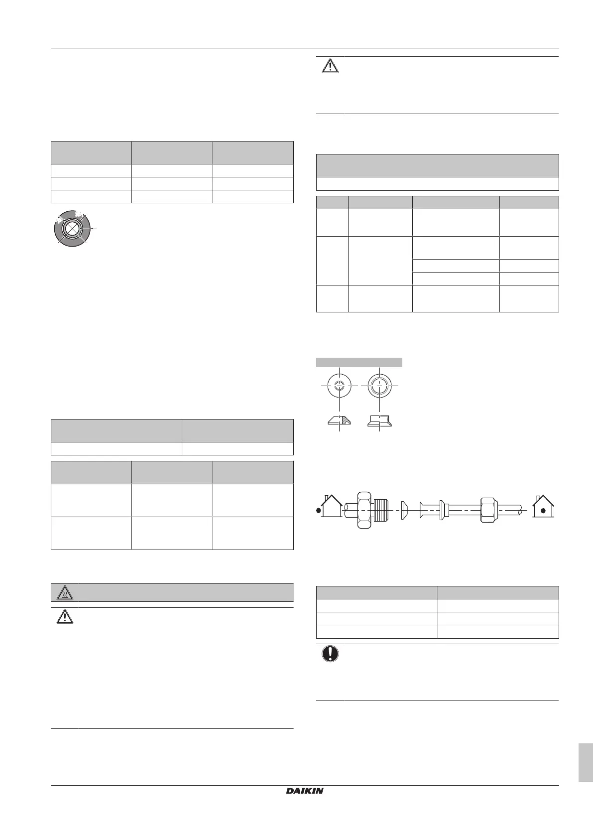
Connection examples:
▪ Connecting a Ø9.5 mm inter unit pipe to a Ø12.7 mm gas pipe
connection port on the outdoor unit
a Reducer 1
b Reducer 2
c Flare nut (on the outdoor unit)
Coat the threaded connection port of the outdoor unit where the flare
nut comes in with refrigeration oil.
Flare nut for (mm) Tightening torque (N•m)
Ø6.4 15~17
Ø9.5 33~39
Ø12.7 50~60
NOTICE
Use an appropriate wrench to avoid damaging the
connection thread by overtightening the flare nut. Be
careful NOT to overtighten the nut, or the smaller pipe may
be damaged (about 2/3-1× the normal torque).
5.2.2 To connect the refrigerant piping to the
outdoor unit
▪ Piping length. Keep field piping as short as possible.
▪ Piping protection. Protect the field piping against physical
damage.
 Loading...