17 | Technical data
Installer reference guide
79
2MXM-A9, 3MXM-A9, 4MXM-A9, 5MXM-A9
R32 Split series
4P600463-7G – 2022.09
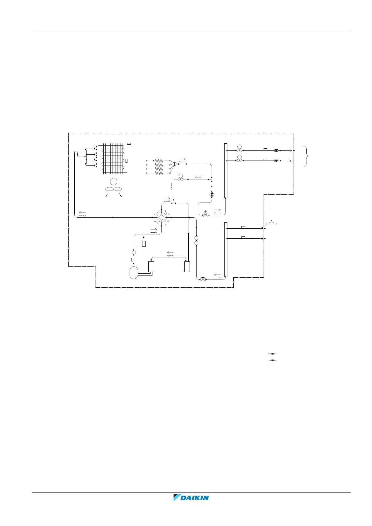
17.2 Piping diagram
17.2.1 Piping diagram: Outdoor unit
Component PED category classification:
▪ High pressure switches: category IV
▪ Compressor: category II
▪ Accumulator: 4MXM80, 5MXM90 category II, other models category I
▪ Other components: refer to PED article 4, paragraph 3
7.9CuT
7.9CuT
7.9CuT
7.9CuT
12.7CuT
M
12.7CuT
(12.7CuT)
(9.5CuT)
12.7CuT
12.7CuT
12.7CuT
15.9CuT
15.9CuT
15.9CuT
15.9CuT
9.5CuT
9.5CuT
12.7CuT
7.9CuT
7.9CuT
MV
MV
A
B
6.4CuT
6.4CuT
(6.4CuT)
(6.4CuT)
9.5CuT
9.5CuT
9.5CuT
9.5CuT
7.9CuT
S1PH
SV
9.5CuT
9.5CuT
6.4CuT
Solenoid valve
12.7CuT
15.9CuT
d
e
f
k
a
b
c
g
i
d
r-A
r-B
s
s
t
t
u
u
d
p
oo
n
l
l
m
l
w
x
v-A
v-B
v-A
v-B
q
h
2MXM68
a Heat exchanger k 4-way valve u Thermistor (gas)
b Outdoor air temperature
thermistor
l Muffler v Room
c Heat exchanger thermistor m Discharge pipe thermistor w Field piping – liquid
d Refnet header n Compressor x Field piping – gas
e Fan motor o Accumulator y Liquid receiver
f Propeller fan p Gas stop valve S1PH High pressure switch
(automatic reset)
g Capillary tube q Liquid stop valve
h Distributor r Electronic expansion valve Refrigerant flow: cooling
i Muffler with filter s Thermistor (liquid) Refrigerant flow: heating
j Solenoid valve t Filter
 Loading...