Page4of16/IOM1178-1
Installation
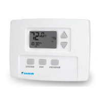
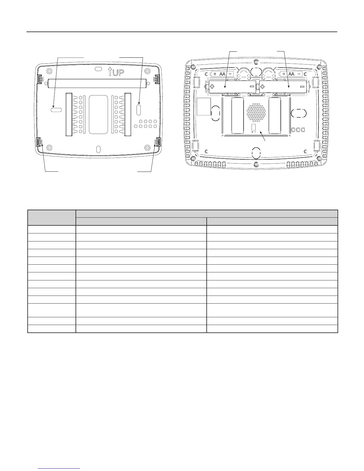
Figure 1: Base & rear view of thermostat
G
RC
RH
C
S
6
W1
-
+
L
Y2
Y
W4
W3
W2
D/A
Stack
Power
Stealing
Switch
Rear View of Thermostat
ON
OFF
G
RC
RH
C
S
6
W1
-
+
L
Y2
Y
W4
W3
W2
D/A
Stack
Power
Stealing
Switch
Thermostat Base
Rear View of Thermostat
ON
OFF
Mounting holes
Place level across mounting tabs
(for appearance only)
"AA" batteries (2)
Power stealing switches
Wiring
Table 4: Thermostat wiring terminals & systems operation
Thermostat Terminal
System
HP1 Operation HP2 Operation
RC 24V power for cooling 24V power for cooling
RH 24V power for heating 24V power for heating
C 24V common 24V common
Y Compressor cool 1st stage Compressor cool 1st stage
Y2 No output Compressor cool 2nd stage
W1 Compressor heat 1st stage Compressor heat 1st stage
W2 No output Compressor heat 2nd stage
W3 Auxiliary heat 1st stage (heat 2nd stage) Auxiliary heat 1st stage (heat 3rd stage)
W4 Heat 2nd stage (heat 3rd stage) Heat 2nd stage (heat 4th stage)
G Fan Fan
DMA/A1
Dehumidicationorwatersideeconomizer,congurableterminal
congurationmenu
Dehumidicationorwatersideeconomizer,congurableterminal
congurationmenu
6 Powered close connection for SPDT 3-wire zone valve Powered close connection for SPDT 3-wire zone valve
L System diagnostic indicator System diagnostic indicator
 Loading...