ParTs and servICe
www.DaikinApplied.com 13 IM 968-4 • MICROTECH III CHILLER UNIT CONTROLLER
ParTs and servICe
Troubleshooting
Follow these procedures if you are not able to communicate
with the chiller via the network:
General
→ Review the Installation and Mounting section of this
document to conrm that all procedures were followed
correctly.
→ Review the Commissioning section of this document
to conrm that all procedures were followed correctly.
→ If the communication module is installed but LEDs are
not active when the unit controller is powered up, remove
the module and then follow the steps provided in the
Installing a new Communication Module section. If the
issue persists, replace the module.
→ Verify that the LON Setup menu appears in the
unit controller keypad/display. If it does not, follow this
procedure:
1. Set the Unit On/Off Switch to “Off” from inside the
control panel of the unit.
2. Remove power from the unit controller, wait 10
seconds, then re-power the chiller unit controller.
Within 45 seconds, the unit controller should
recognize the attached communication module, and
will cycle power.
3. Verify that the LON Setup menu now appears in the
unit controller keypad/display.
Network Wiring and Connections
→ Check for faulty cable connectors at the chiller
LonWorks communication module and throughout the
network.
→ Determine if there is a network ground fault.
→ For network terminal connections, twist the wires
together a minimum of three times.
→ Use only approved cable. Do not use different wire
types on the same bus.
→ Follow the bus length limits for the cable type.
→ Conrm that you have the correct transceiver.
→ Make sure that the network trunk avoids strong
sources of electromagnetic interference (EMI).
→ Verify that the network trunk is not located near a DC
load switch (relay).
Bus terminators
Errors from bus termination can have the following results:
• Signal level too low could indicate the wrong bus
terminator or too many terminators.
• Signal level too high could indicate a high-level signal
or signal reections point due to a missing or wrong bus
terminator, or that bus terminators are placed incorrectly.
→ Verify that the correct terminators are used based on
your network topology.
• Free topology should have a single 52.3 Ω bus
terminator at busiest point of network.
• Line topology should have two (2) 105 Ω bus
terminators at both network ends.
Network Performance
→ If network trafc is slow, communication is intermittent,
or the trunk is experiencing “noise,” it may be necessary
to use a network protocol analyzer or oscilloscope to
determine the source of poor performance.
→ Conrm power is applied to the unit controller.
Contact the Daikin Applied Controls Customer Support Group
at 866-462-7829 for additional assistance, if necessary.
Parts
Table 4: Replacement Parts List
Description Part Number
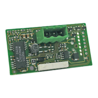
MicroTech III LonWorks communication module kit
Kit includes: LonWorks communication module, board-
to-board connector, and IM 968
350147412
2-pin network connector plug (Figure 4) 193410302
10-pin board-to-board connector (Figure 6) 300047027
To nd your local parts ofce, visit www.DaikinApplied.com or
call 800-37PARTS (800-377-2787).
 Loading...
