IM 968-4 • MICROTECH III CHILLER UNIT CONTROLLER 6 www.DaikinApplied.com
InTroduCTIon
Light Emitting Diodes (LEDs)
The LonWorks communication module has two LEDs that
indicate communication activity and network status. These
indicators are visible when the communication module is
connected to the MicroTech III chiller unit controller and the unit
is powered on (Figure 4).
BSP LED
The BSP LED indicates the communication state between
the LonWorks communication module and the unit controller
(Table 1).
Table 1: BSP LED Activity
BSP LED Color Description
Flashing that alternates
between red and green
Board Support Package (BSP) rmware upgrade
in progress.
Green
Communication is established between the
communication module and the unit controller.
Yellow
The communication module is capable of
communicating to the unit controller. However,
communication is not established.
Flashing between red and
yellow
Download the BSP rmware again. For BSP
versions 9.26 and newer, the communication
module enters a fail-safe mode
1
after the initial
BSP download is performed. However, two
downloads are required.
Red ashing with 2Hz BSP (rmware) error.
2
Red Hardware error.
1. The fail-safe mode does not apply to communication modules with BSP
versions older than 9.26.
2. In the event that this should occur, cycle power to the unit controller. Contact
the Daikin Applied Controls Customer Support Group at 866-462-7829 for
additional assistance if necessary.
BUS LEDs
The BUS LED indicates the communication status between the
LonWorks communication module and the network (Table 2).
Table 2: BUS LED Activity
BUS LED Color Description
Green
The unit controller is capable of communicating to the
network.
Yellow The communication module is initializing.
Yellow ashing
The unit controller has not yet communicated with the
network.
Red Hardware error.
LonWorks Network Connector
The network connector is the physical connection between the
LonWorks communication module and the FTT-10A bus. Two
pins are used for this purpose as indicated below and shown in
Figure 4.
Pin Function
CLA FTT-10A
CLB FTT-10B
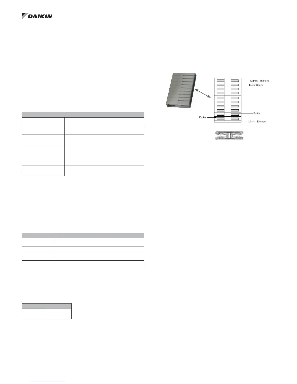
Board-To-Board Connector
The 10-pin board-to-board connector connects the MicroTech
III chiller unit controller to the LonWorks communication
module (Figure 6 and Figure 8).
Figure 6: Board-to-Board Connector
Neuron ID
The basis of the LonWorks communication module is an
Echelon Neuron integrated circuit (Neuron chip). Every Neuron
chip has a unique 48-bit Neuron ID or physical address. The
Neuron ID can be used to address the device on the LonWorks
network.
The Neuron ID is generally used only during initial installation
or for diagnostic purposes. For normal network operation, a
device address is used.
Transceiver
The LonWorks communication module is equipped with an
Echelon Free Topology Transceiver (FTT-10A) to enable
network communication. The transceiver supports free
network topology (including ring, star, and daisy-chain)
using unshielded, twisted pair cable with polarity insensitive
connections at each node. Free topology segments require
termination for proper transmission performance.
Data transmission rate on the network is 78 kbps (baud).

 Loading...


