Installation and operation manual
14
FWEC3
Advanced plus electr
onic controller
FC66002765
MODBUS
The pr
otocol implemented in the controller is Modbus RTU
(9600, N, 8, 2) on RS485
FUNCTIONS IMPLEMENTED
■ 0x03 : Read Holding Registers
■ 0x04 : Read Input Registers
■ 0x10 : Write Multiple registers
EXCEPTIONS IMPLEMENTED
Exception Code 02: Invalidate data address
LIST OF SUPERVISION PARAMETERS
ADDRESS
REGISTER TYPE U.O.M.
0
Status
R-
1
Speed
R-
2
Air temperature
R [°C/10]
3
Humidity
R%
4
Water temperature
R [°C/10]
5
P00: Confi guration
R-
6
P05: DIN Confi g.
R-
7
T. Active setpoint
R [°C/10]
8
T. User setpoint
R [°C/10]
9
LCD version
R-
10
P09: DOUT1 Confi g.
R
11
P10: DOUT1 Logic
R
12
P11: DOUT2 Confi g.
R
13
P12: DOUT2 Logic
R
14
P14: AOUT1/2 Confi g.
R
15
Analog output 1
R [%]
16
Analog output 2
R [%]
50
Digital 1
R/W -
51
Hourly programming
R/W -
52
Setpoint - Cooling
R/W [°C/10]
53
Setpoint - Heating
R/W [°C/10]
54
Minimum Setpoint – Cool.
R/W [°C/10]
55
Maximum Setpoint – Cool.
R/W [°C/10]
56
Minimum Setpoint – Heat.
R/W [°C/10]
57
Maximum Setpoint – Heat.
R/W [°C/10]
58
Speed
R/W -
59
Economy Correction
R/W [°C/10]
60
Modulating fan mode
R/W -
ALARMS
This contr
ol governs two types of alarms:
■ Serious Alarms cause the forced switching off of the ther-
mostat
■ Non-serious Alarms do not cause the forced switching off
of the thermostat, but disable possible critical functions
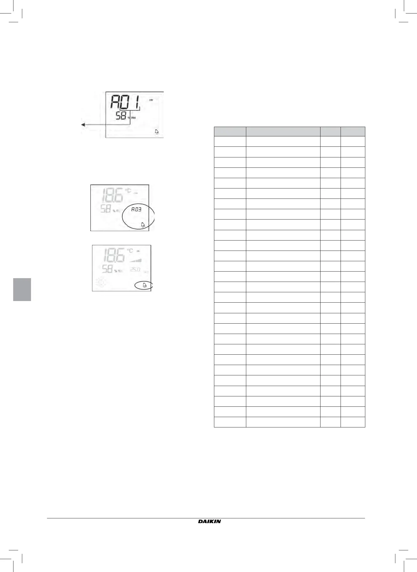
SERIOUS ALARMS
■
Code A01 = error of external air temperature sensor (in case
of on-board thermostat)
■ Code A02 = error of internal air temperature sensor (in case
of wall mounted thermostat and disconnected external air
temperature sensor)
NON-SERIOUS ALARMS
THERMOST
AT OFF
THERMOST
AT ON
■ Code A03 = water sensor err
or
■ Code A04 = external humidity probe error (only if a remote
temperature sensor is installed)
■ Code A05 = internal humidity probe error
N.B.: the alarm code is displayed only when the ther-
mostat is switched off
Alarm code
 Loading...


