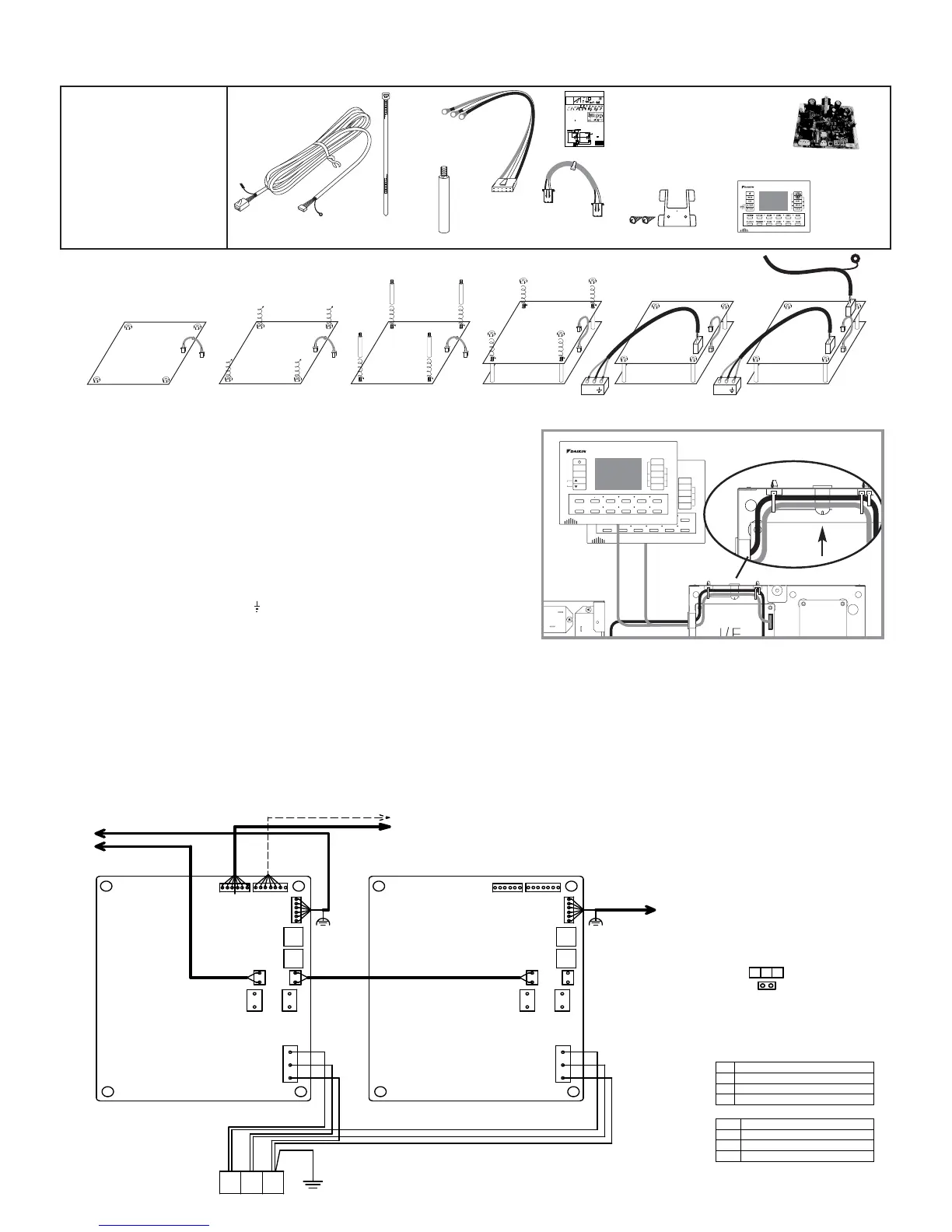
1. Insert one end of P1/P2 harness into socket S9 located on the lower interface
PCB (A1P). Diagram 1.
2. Loosen (4) plastic nuts. Diagram 2.
3. Screw in (4) PCB post and gently tighten. Diagram 3
4. Install upper Interface PCB (A2P) in the same direction as lower Interface
PCB (A1P). Diagram 4.
5. Add (4) plastic nuts and gently tighten. Diagram 4.
6. Plug the loose end of P1/P2 harness into socket S7 of upper Interface PCB
(A2P). Diagram 4.
7. Wire Power harness into LN terminal block X3M (Black- L)
(White –N) (Green – Earth). Diagram 5.
8. Plug the other end of the power harness into S1 socket of the upper Interface
PCB (A2P). Diagram 5.
9. Pass the Remote controller cable through the 2 open cable ties. If the cable
ties have already been tightened cut the cable ties and use the spare cable
ties supplied to secure the controller leads. Diagram 7.
10. Plug the remote controller cable connector into socket S8 of upper Interface
PCB (A2P). Diagram 6.
11. Secure the earth shield to the earth shield post. Diagram 7.
TO REMOTE CONTROLLER
TO RELAY PCB S19 (8 ZONE ONLY)
TO RELAY PCB S19 (4 ZONE)
A2PA1P
L NE
S12
S7 S9
S2
S1 S1
S3
S13 S12 S13
S8
TN1
(NOTE 2)
TN2
S7 S9
S2 S3
S8
TO SUB CONTROLLER
TN1
TN2
TO P1 P2 TERMINAL
BLOCK (NOTE1)
B W G X3M
Sub Controller Instructions BRCSZC
S9
S9 S9
S9
S1
L N
S7
1 2 3 4 5 6
7
S9
S8
L N
ACCESSORIES
CABLE
TIE
X 5
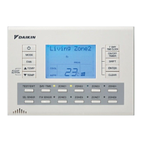
SUB ZONE
KEYPAD
X 1
P1/P2
HARNESS
X 1
POWER
HARNESS
X 1
PCB
POST
X 4
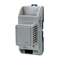
INTERFACE
PCB X 1
15M
CONTROLLER
CABLE
X 1
Remote controller wiring
ANE
ANE
S7
MODE
FAN
TEMP
ADJUST
BUTTON
TEMP
SHIFT
7 DAY
TIME CLOCK
ON/OFF
TIMER
ENTER
CLEAR
TEST/EXIT DAY TIME ZONE1 ZONE2 ZONE3 ZONE4
SEL SENSOR
FIX
SENSOR
ZONE5 ZONE6 ZONE7 ZONE8
MODE
FAN
TEMP
ADJUST
BUTTON
TEMP
SHIFT
7 DAY
TIME CLOCK
ON/OFF
TIMER
ENTER
CLEAR
TEST/EXIT DAY TIME ZONE1 ZONE2 ZONE3 ZONE4
SEL SENSOR
FIX
SENSOR
ZONE5 ZONE6 ZONE7 ZONE8
4PDA0687
NOTE:
1. P1 P2 TERMINAL BLOCK
LOCATED IN THE ELECTRICAL
BOX OF INDOOR UNIT.
2. TN1, TN2 ONLY USE DAIKIN
REMOTE TEMPERATURE
SENSOR KRCSO1-1
3. :TERMINAL
:CONNECTOR
4. SYMBOLS SHOW AS FOLLOWS
B: BLACK
W: WHITE
G: GREEN
A1P INTERFACE PRINTED CIRCUIT BOARD
A2P INTERFACE PRINTED CIRCUIT BOARD
TN1 REMOTE SENSORS 1
TN2 REMOTE SENSORS 2
S1
S9-S7
S7
S8
CONNECTOR
230~240V
A1P 7 A2P COMMUNICATION
A1P INDOOR COMMUNICATION
REMOTE CONTROLLER
A1P
A2P
X3M
SCREW
X 2
MOUNTING
BRACKET
X 1
INSTALLATION
INSTRUCTION
X 1
1. Insert one end of P1/P2 harness into socket S9 located on the lower interface
PCB (A1P). Diagram 1.
2. Loosen (4) plastic nuts. Diagram 2.
3. Screw in (4) PCB post and gently tighten. Diagram 3
4. Install upper Interface PCB (A2P) in the same direction as lower Interface
PCB (A1P). Diagram 4.
5. Add (4) plastic nuts and gently tighten. Diagram 4.
6. Plug the loose end of P1/P2 harness into socket S7 of upper Interface PCB
(A2P). Diagram 4.
7. Wire Power harness into LN terminal block X3M (Black- A)
(White –N) (Green – Earth). Diagram 5.
8. Plug the other end of the power harness into S1 socket of the upper Interface
PCB (A2P). Diagram 5.
9. Pass the Remote controller cable through the 2 open cable ties. If the cable
ties have already been tightened cut the cable ties and use the spare cable
ties supplied to secure the controller leads. Diagram 7.
10. Plug the remote controller cable connector into socket S8 of upper Interface
PCB (A2P). Diagram 6.
11. Wire the controller lead earth shield cable to the earth shield post. Diagram 7.
TO REMOTE CONTROLLER
TO RELAY PCB S19 (8 ZONE ONLY)
TO RELAY PCB S19 (4 ZONE)
A2PA1P
LNE
S12
S7S8
S2
S1 S1
S3
S13 S12 S13
S8
TN1
(NOTE 2)
TN2
S7S8
S2 S3
S8
TO SUB CONTROLLER
TN1
TN2
TO P1 P2 TERMINAL
BLOCK (NOTE1)
BWGX3M
Sub Controller Instructions BRCSZC
S9
S9 S9
S9
S1
A N
S7
1
2 3 4
5 6
7
S9
S8
A N
ACCESSORIES
CABLE
TIE
X 5
SUB ZONE
KEYPAD
X 1
P1/P2
HARNESS
X 1
POWER
HARNESS
X 1
PCB
POST
X 4
INTERFACE
PCB X 1
15M
CONTROLLER
CABLE
X 1
Remote controller wiring
ANE
ANE
S7
MODE
FAN
TEMP
ADJUST
BUTTON
TEMP
SHIFT
7 DAY
TIME CLOCK
ON/OFF
TIMER
ENTER
CLEAR
TEST/EXITDAY TIMEZONE1ZONE2 ZONE3ZONE4
SEL SENSOR
FIX
SENSOR
ZONE5ZONE6 ZONE7 ZONE8
MODE
FAN
TEMP
ADJUST
BUTTON
TEMP
SHIFT
7 DAY
TIME CLOCK
ON/OFF
TIMER
ENTER
CLEAR
TEST/EXITDAY TIMEZONE1ZONE2 ZONE3ZONE4
SEL SENSOR
FIX
SENSOR
ZONE5ZONE6 ZONE7 ZONE8
4PDA0687
NOTE:
1. P1 P2 TERMINAL BLOCK
LOCATED IN THE ELECTRICAL
BOX OF INDOOR UNIT.
2. TN1, TN2 ONLY USE DAIKIN
REMOTE TEMPERATURE
SENSOR KRCSO1-1
3. :TERMINAL
:CONNECTOR
4. SYMBOLS SHOW AS FOLLOWS
B: BLACK
W: WHITE
G: GREEN
A1P INTERFACE PRINTED CIRCUIT BOARD
A2P INTERFACE PRINTED CIRCUIT BOARD
TN1 REMOTE SENSORS 1
TN2 REMOTE SENSORS 2
S1
S9-S7
S7
S8
CONNECTOR
230~240V
A1P 7 A2P COMMUNICATION
A1P INDOOR COMMUNICATION
REMOTE CONTROLLER
A1P
A2P
X3M
SCREW
X 2
MOUNTING
BRACKET
INSTALLATION
INSTRUCTIONS
INSTALLATION MANUAL
ZONE CONTROLLER
Air Conditioners
MODELS
BRC230Z4
BRC230Z8
BRC24Z4
BRC24Z8
BRCSZC
PLEASE READ THESE INSTRUCTIONS CAREFULLYBEFORE INSTALLATION.
KEEPTHIS MANUALIN AHANDY PLACE FOR FUTURE REFERENCE.
 Loading...