OM 931-6 • MicroTech III Unit Controller for WSHP 17 www.DaikinApplied.com
operatIon
Dual Circuit Units
• Provides standard lead / lag operation for two
compressors in dual circuit units
• The lag circuit will be enabled after the interstage
timer has expired. The interstage timer defaults to
300 seconds
• HP, LP, SLTS fault for either circuit one or circuit two,
will lockout the individual compressor.
Thermostat Inputs (Y2, W2)
• The Y2 terminal which is cooling mode stage two,
energizes the lag compressor
• If Y1 and Y2 thermostat inputs are active at the same
time, interstage timers will be used to stage the
compressor up and down
• The W2 terminal which is heating mode stage two,
energizes the lag compressor.
• If W1 and W2 thermostat inputs are active at the
same time, interstage timers will be used to stage the
compressors up and down
Electric Heat Controls
Boilerless Heat Coil Control
• Turns on the factory installed heater when the water
loop uid entering water temperature is less than
55°F. The xed 55°F is used when jumper JP3
setting is open
• For geothermal applications (glycol loop uid),
the factory installed electric heater turns on when
the entering water temperature is less than 28°F.
The xed 28°F is used when jumper JP3 setting is
shorted
Note: In both cases the compressor is shut down.
Multiple Speed Fan Control
• When the Water Source Heat Pump is equipped
with an I/O Expansion Module and factory installed
electric heat, three speed fan control is possible.
• If the thermostat is calling for continuous fan
operation and the compressor is not running the fan
motor will run in low speed.
• If there is a call for heating or cooling (compressor is
running) the fan motor will run in medium speed.
• If the electric heater is enabled the fan motor will run
in high speed.
Note: On units with an I/O Expansion Module and no
electric heat, it is possible to congure the I/O
Expansion Module for a two speed fan. If there is
a call for continuous fan (compressor off) the fan
motor runs in low speed. If there is a call for heat-
ing or cooling (compressor on) the fan motor runs
at high speed.
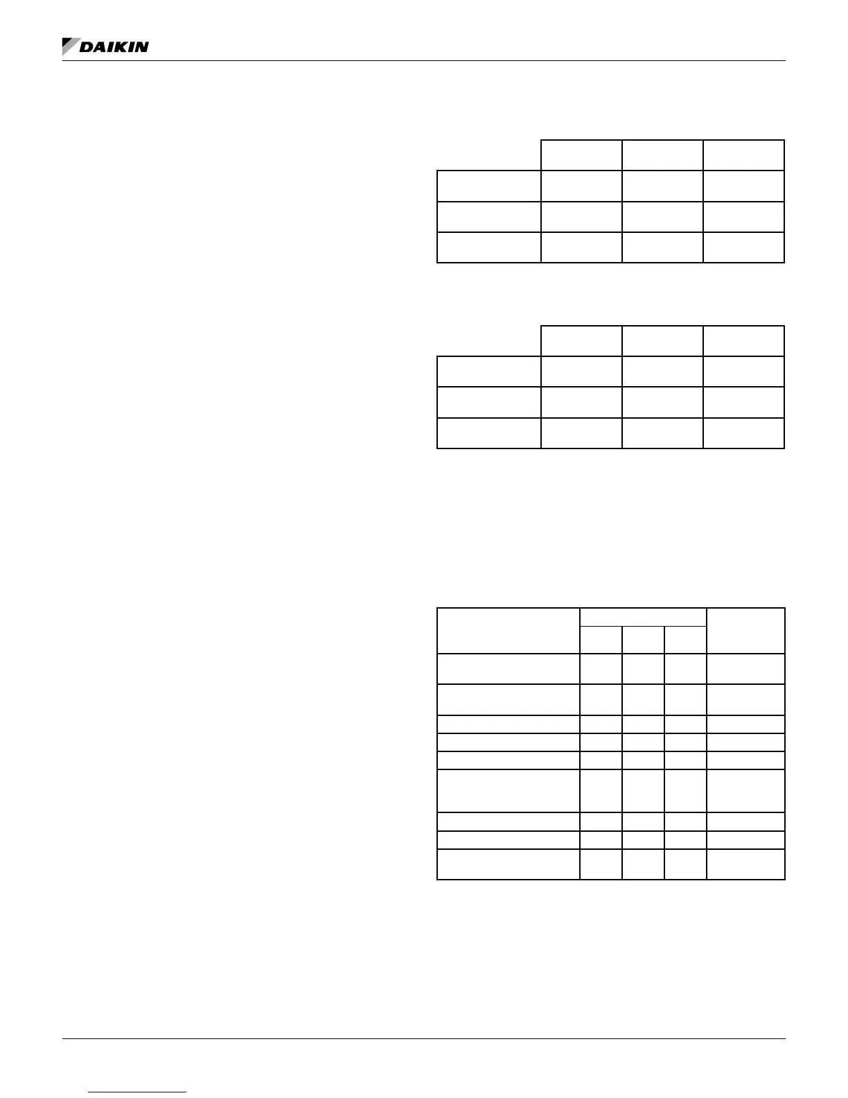
Three-Speed Fan Operations
Table 8: Three-Speed Fan
Continuous
Fan
Compressor
On
Electric Heat
Space Temp
Satised
Low Speed Off Off
Compressor
Heating/Cooling
Off Med. Speed Off
Electric Heat
Enabled
Off Off High Speed
Two-Speed Fan Operations
Table 9: Two-Speed Fan
Continuous
Fan
Compressor
On
Electric Heat
Space Temp
Satised
Low Speed Off Off
Compressor
Heating/Cooling
Off High Speed Off
Electric Heat
Enabled
Off Off High Speed
Circuit Two, Additional Operating
Modes
The I/O Expansion Module controls the second circuit
high pressure, low pressure, and low suction line
temperature operating conditions in the same manner as
the main board controls the rst circuit.
Table 10: I/O Expansion Module LED & Fault Outputs
Mode / Fault
Status LED's
Thermostat
Output
Terminal “A”
Yellow Green Red
Invalid Conguration Jumper
Setting
Flash Flash Off De-energized
Base Board Communication
Failure
Off Flash Flash N/A
High Pressure #2 Fault Off Off Flash De-energized
Low Pressure #2 Fault Off Off On De-energized
Low Suction Temp #2 Fault Flash Off Off De-energized
Sensor Failures Low Suction
Low Suction Temp #2,
1
EWT (w/ Boilerless EH only)
Flash Flash On De-energized
2
Service Test Mode Enabled Flash Flash Flash Energized
Unoccupied Mode On On Off Energized
Occupied, Bypass, Standby,
or Tenant Override Modes
Off On Off Energized
Note: All conditions in table 10 are with conguration jumper JP4 open on the
main control board. Mode / Faults are listed in order of priority.
1
Boilerless electric heat only
2
Alarm/fault LED indications take precedence over service
test mode LED indication. The controller shall use service
test mode if the service test mode jumper is installed, even if
the LED’s indicate an alarm/fault.

 Loading...


