OM 931-6 • MicroTech III Unit Controller for WSHP 18 www.DaikinApplied.com
operatIon
Second Circuit Faults
With the addition of the second circuit the fault recovery and reset table has new faults for the second circuit. Refer to
"Table 3: Faults" on page 11.
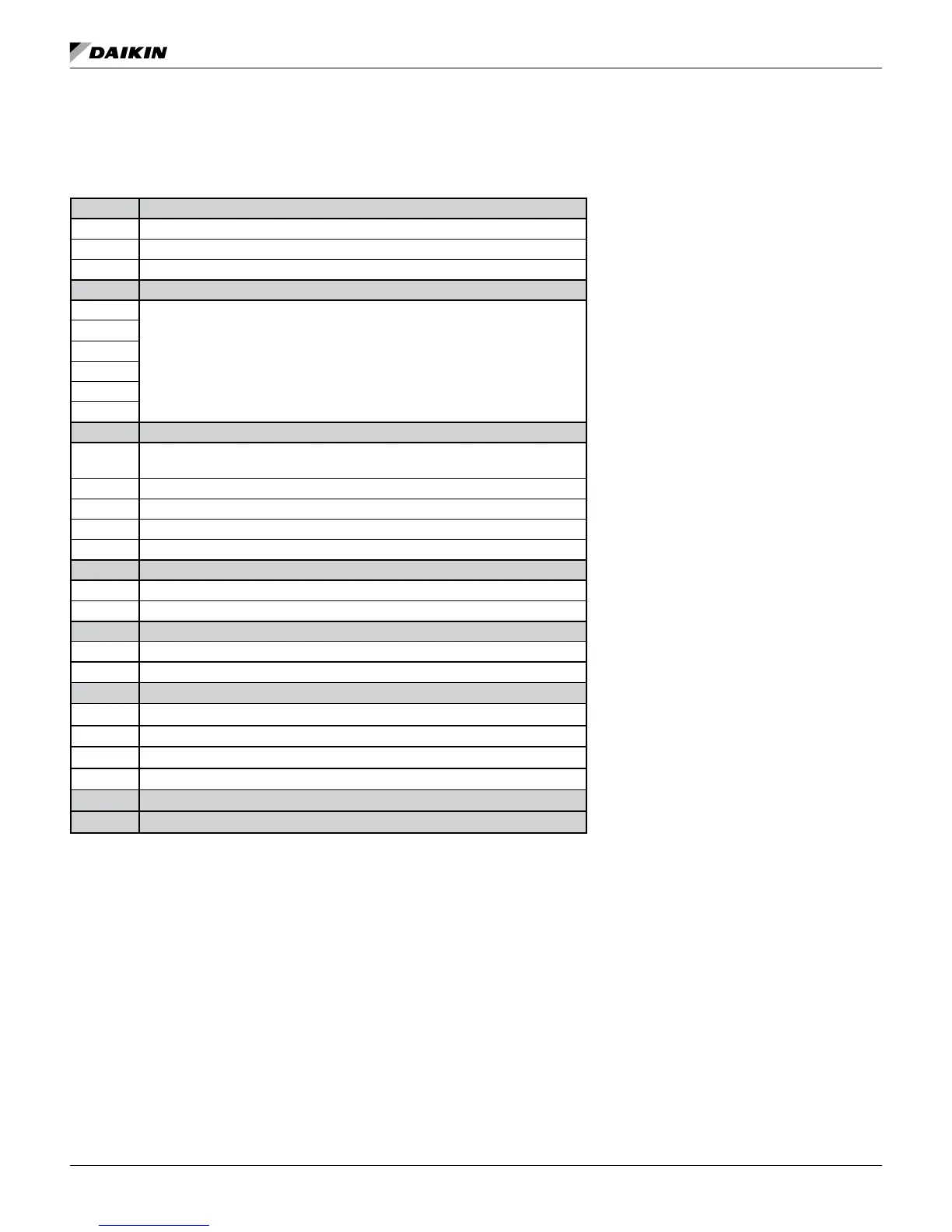
Table 11: I/O Expansion Module Connections & Descriptions
H2 Description
Pin 1 Fan high speed normally open output
Pin 2 No connection
Pin 3 24 VAC Common
H3
Pin 1
For future development
Pin 2
Pin 3
Pin 4
Pin 5
Pin 6
H8
Pin 1
Dual compressor: compressor 2 normally open output, all others fan medium speed
normally open
Pin 2 24 VAC common
Pin 3 No connection
Pin 4 Dual compressor: reversing valve for circuit 2, all others electric heat
Pin 5 24 VAC common
H4
Pin 1 Entering water temperature sensor signal
Pin 2 Entering water temperature sensor common
HP6
HP2-1 High pressure switch for circuit 2
HP2-2 High pressure switch for circuit 2
H7
Pin 1 Suction line temperature sensor circuit 2 signal
Pin 2 Suction line temperature sensor circuit 2 common
Pin 3 Low pressure switch circuit 2 signal
Pin 4 Low pressure switch circuit 2 source
H5 LED Annunciator
TB1 For future use

 Loading...


