5 Unit installation
Installation manual
4
CTXM15+FTXM20~42+ATXM20~35R2/5V1B +
FTXM50~71R2V1B + ATXM50R2V1B
Daikin room air conditioner
3P482320-11R – 2020.06
4.1 About the wireless LAN
For detailed specifications, installation instructions, setting methods,
FAQ, declaration of conformity and the latest version of this manual,
visit http://www.onlinecontroller.daikineurope.com.
INFORMATION
▪ Daikin Industries Czech Republic s.r.o. declares that
the radio equipment type inside of this unit is in
compliance with Directive 2014/53/EU.
▪ This unit is considered as combined equipment
according to the definition of Directive 2014/53/EU.
4.1.1 Precautions when using the wireless LAN
Do NOT use near:
▪ Medical equipment. E.g. persons using cardiac pacemakers or
defibrillators. This product may cause electromagnetic
interference.
▪ Auto-control equipment. E.g. automatic doors or fire alarm
equipment. This product may cause faulty behaviour of the
equipment.
▪ Microwave oven. It may affect wireless LAN communications.
4.1.2 Basic parameters
What Value
Frequency range 2400MHz~2483.5MHz
Radio protocol IEEE 802.11b/g/n
Radio frequency channel 1~13
Output power 13dBm
Effective radiated power 15dBm (11b) / 14dBm (11g) /
14dBm (11n)
Power supply DC 14 V / 100 mA
5 Unit installation
5.1 Preparing the installation site
WARNING
The appliance shall be stored in a room without
continuously operating ignition sources (example: open
flames, an operating gas appliance or an operating electric
heater).
5.1.1 Installation site requirements of the
indoor unit
INFORMATION
The sound pressure level is less than 70dBA.
▪ Air flow. Make sure nothing blocks the air flow.
▪ Drainage. Make sure condensation water can be evacuated
properly.
▪ Wall insulation. When conditions in the wall exceed 30°C and a
relative humidity of 80%, or when fresh air is inducted into the
wall, then additional insulation is required (minimum 10 mm
thickness, polyethylene foam).
▪ Wall strength. Check whether the wall or the floor is strong
enough to support the weight of the unit. If there is a risk, reinforce
the wall or the floor before installing the unit.
▪ Spacing. Install the unit at least 1.8m from the floor and keep the
following requirements in mind for distances from the walls and
the ceiling:
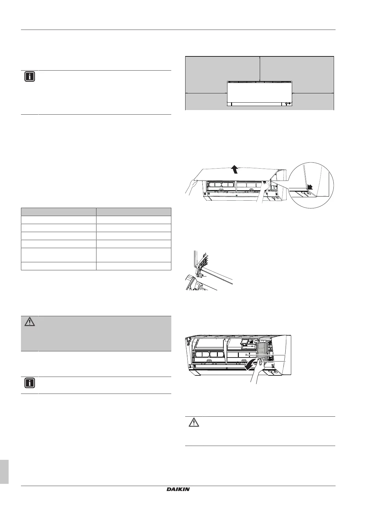
5.2 Opening the indoor unit
5.2.1 To remove the front panel
1 Hold the front panel by the panel tabs on both sides and open
it.
2 Remove the front panel by sliding it to the left or the right and
pulling it toward you.
Result: The front panel shaft on 1 side will be disconnected.
3 Disconnect the front panel shaft on the other side in the same
manner.
a Front panel shaft
5.2.2 To open the service cover
1 Remove 1 screw from the service cover.
2 Pull out the service cover horizontally away from the unit.
a Service cover screw
b Service cover
5.2.3 To remove the front grille
CAUTION
Wear adequate personal protective equipment (protective
gloves, safety glasses,…) when installing, maintaining or
servicing the system.
1 Remove the front panel to remove the air filter.
2 For class 50~71 remove the flap (horizontal blade). Push the
blade on its left side to the centre and unhook it. Push blade on
its right side to centre to unhook it from shaft. Disconnect the 2
centre connection points.
 Loading...